4
DV-410V-S
1
2
3
4
A
B
C
D
E
F
1
2
3
4
CONTENTS
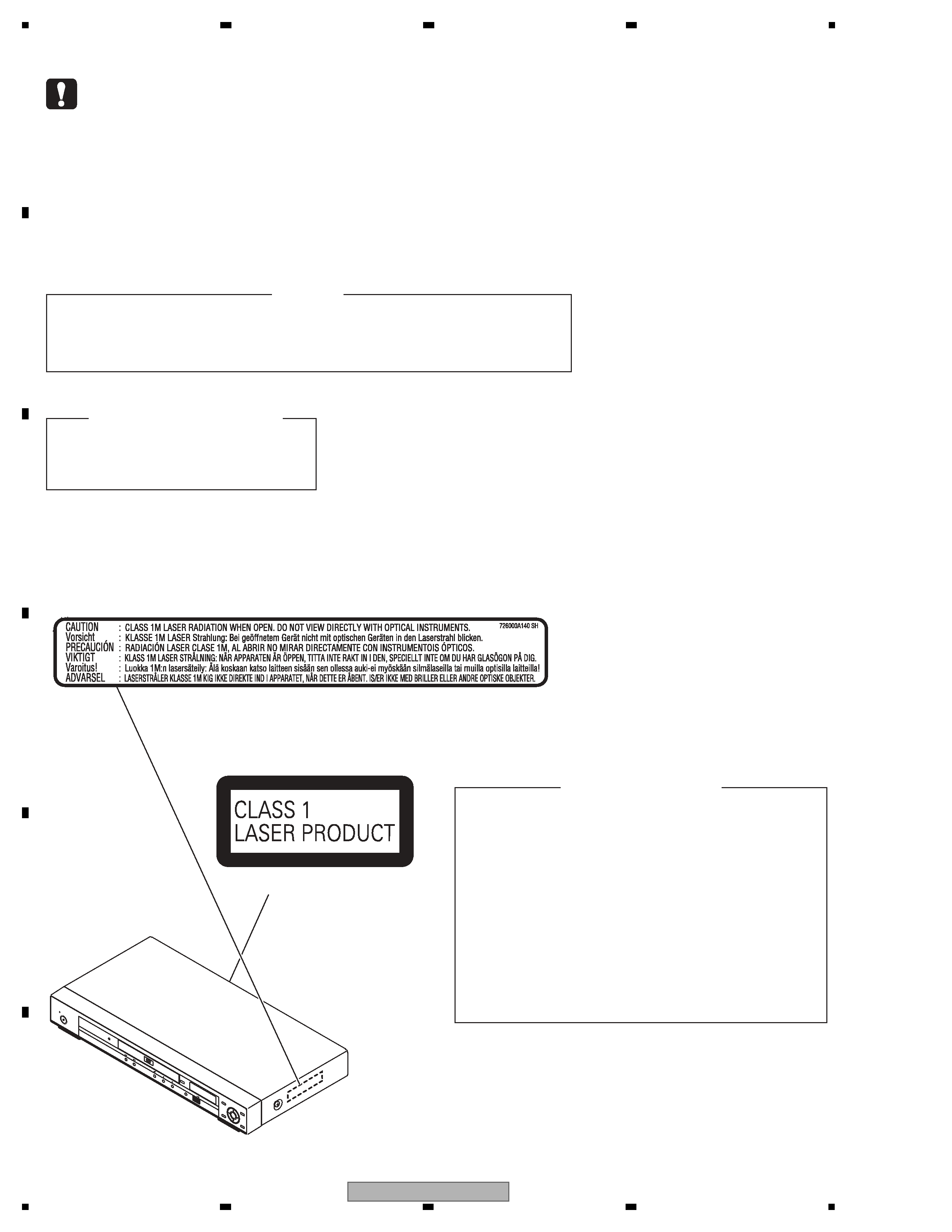
SAFETY INFORMATION ..........................................................................................................................................................2
1. SERVICE PRECAUTIONS ....................................................................................................................................................5
2. SPECIFICATIONS .................................................................................................................................................................7
2.1 ACCESSORIES ..............................................................................................................................................................7
2.2 SPECIFICATIONS...........................................................................................................................................................8
2.3 DISC/CONTENT FORMAT .............................................................................................................................................9
2.4 PANEL FACILITILES .....................................................................................................................................................11
3. BASIC ITEMS FOR SERVICE.............................................................................................................................................13
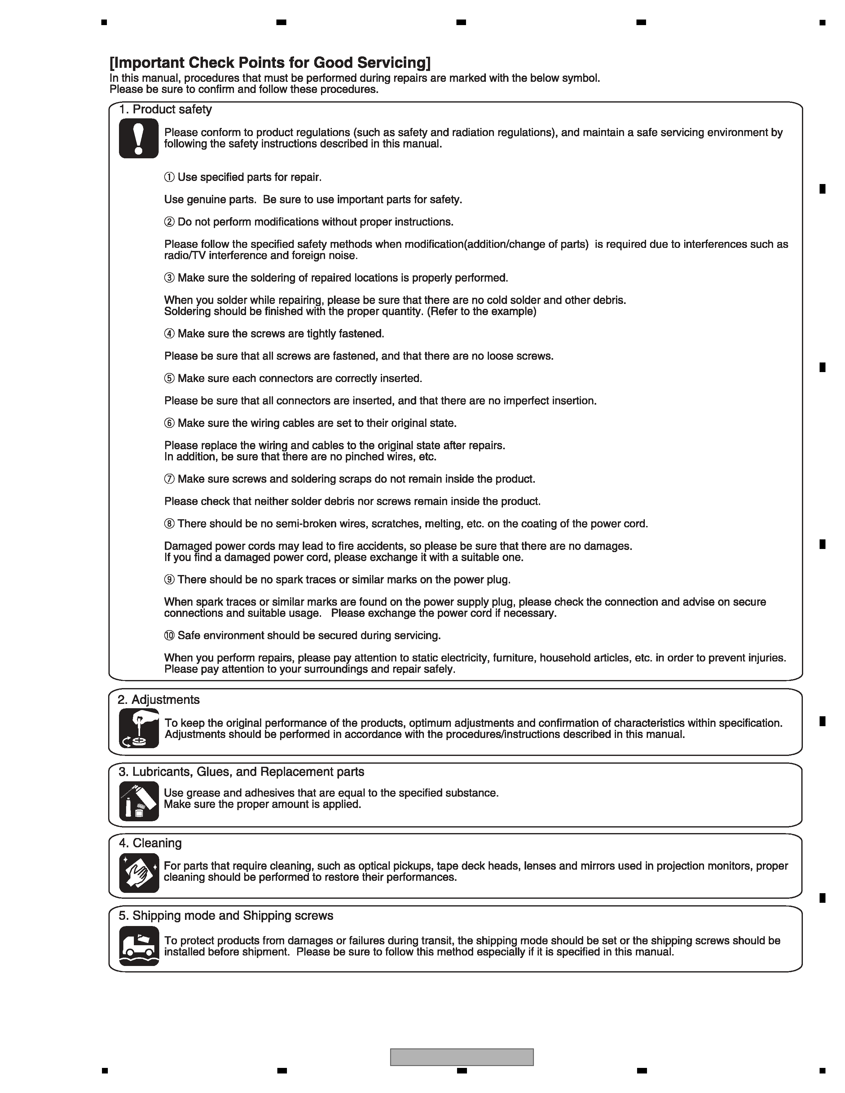
3.1 CHECK POINTS AFTER SERVICING..........................................................................................................................13
3.2 PCB LOCATIONS .........................................................................................................................................................14
3.3 JIGS LIST .....................................................................................................................................................................15
4. BLOCK DIAGRAM...............................................................................................................................................................16
4.1 OVERALL WIRING DIAGRAM......................................................................................................................................16
4.2 OVERALL BLOCK DIAGRAM.......................................................................................................................................18
4.3 DVD LOADER/MPEG BLOCK DIAGRAM.....................................................................................................................19
4.4 POWER BLOCK DIAGRAM..........................................................................................................................................20
5. DIAGNOSIS.........................................................................................................................................................................21
5.1 TROUBLE SHOOTING .................................................................................................................................................21
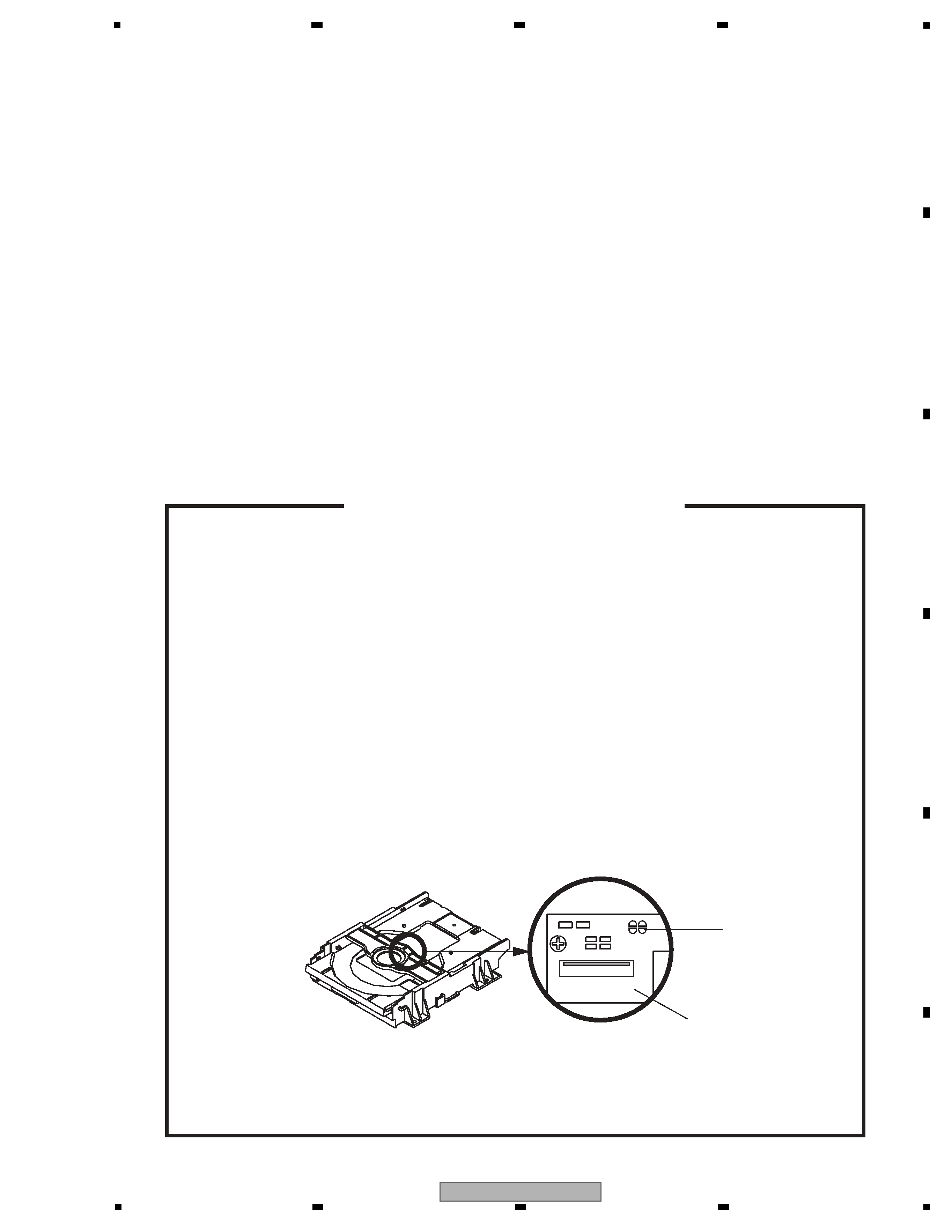
5.2 METHOD FOR DIAGNOSING DEGRADATION OF THE LDS ON THE PICKUP ASSY .............................................25
6. SERVICE MODE .................................................................................................................................................................26
6.1 SERVICE MODE PROCEDURE...................................................................................................................................26
6.2 SERVICE MODE IN ......................................................................................................................................................27
6.3 DISPLAY SPECIFICATION OF THE SERVICE MODE ................................................................................................28
6.4 FUNCTIONAL SPECIFICATION OF THE SHORTCUT KEY........................................................................................29
6.5 FUNCTIONAL SPECIFICATION OF THE SERVICE MODE ........................................................................................30
7. DISASSEMBLY....................................................................................................................................................................31
7.1 EXTERIOR SECTION...................................................................................................................................................31
7.2 DVD DECK SECTION...................................................................................................................................................32
8. EACH SETTING AND ADJUSTMENT ................................................................................................................................36
8.1 ADJUSTMENT ..............................................................................................................................................................36
8.2 RE-WRITE FOR DVD FIRMWAVE ...............................................................................................................................36
9. EXPLODED VIEWS AND PARTS LIST...............................................................................................................................38
9.1 PACKING ......................................................................................................................................................................38
9.2 EXTERIOR SECTION...................................................................................................................................................40
9.3 06 DVD MECHA SECTION...........................................................................................................................................42
10. SCHEMATIC DIAGRAM ....................................................................................................................................................44
10.1 DVD MT PCB ASSY(1/7) ............................................................................................................................................44
10.2 DVD MT PCB ASSY(2/7) ............................................................................................................................................46
10.3 DVD MT PCB ASSY(3/7) ............................................................................................................................................48
10.4 DVD MT PCB ASSY(4/7) ............................................................................................................................................50
10.5 DVD MT PCB ASSY(5/7) ............................................................................................................................................52
10.6 DVD MT PCB ASSY(6/7) ............................................................................................................................................54
10.7 DVD MT PCB ASSY(7/7) ............................................................................................................................................56
10.8 OPERATION PCB ASSY ............................................................................................................................................58
10.9 POWER PCB ASSY(1/2) ............................................................................................................................................60
10.10 POWER PCB ASSY(2/2) ..........................................................................................................................................62
10.11 WAVEFORMS ...........................................................................................................................................................64
11. PCB CONNECTION DIAGRAM ........................................................................................................................................66
11.1 DVD MT PCB ASSY....................................................................................................................................................67
11.2 OPERATION PCB ASSY ............................................................................................................................................69
11.3 POWER PCB ASSY....................................................................................................................................................70
11.4 LOADING MOTOR and SW ........................................................................................................................................72
12. PCB PARTS LIST ..............................................................................................................................................................73