PIONEER DJM-800/KUCXJ Owner's Manual

Cover page of PIONEER DJM-800/KUCXJ Owner's Manual

Owner's Manual for PIONEER DJM-800/KUCXJ, downloadable as a PDF file.

We also have service manual to this model.

Manual details

  • Immediate download after payment.
  • Delivered as a PDF file.
  • The manual has 24 pages
  • File size: 1.14 MB
  • Available language versions: French, English
  • Different language versions may vary sligthly in file size and page count.

We guarantee that...

  • our manuals are complete,
  • our manuals are checked with antivirus,
  • We'll issue refund if the manual is damaged, incomplete or unreadable (our refund policy)

Sample pages

Thumbnail of page 1Thumbnail of page 2Thumbnail of page 3Thumbnail of page 4
Thumbnail of page 5Thumbnail of page 6Thumbnail of page 7Thumbnail of page 8
Thumbnail of page 9
background image
Operating Instructions
DJ MIXER
DJM-800
background image
Operating Instructions
DJ MIXER
DJM-800
background image
2
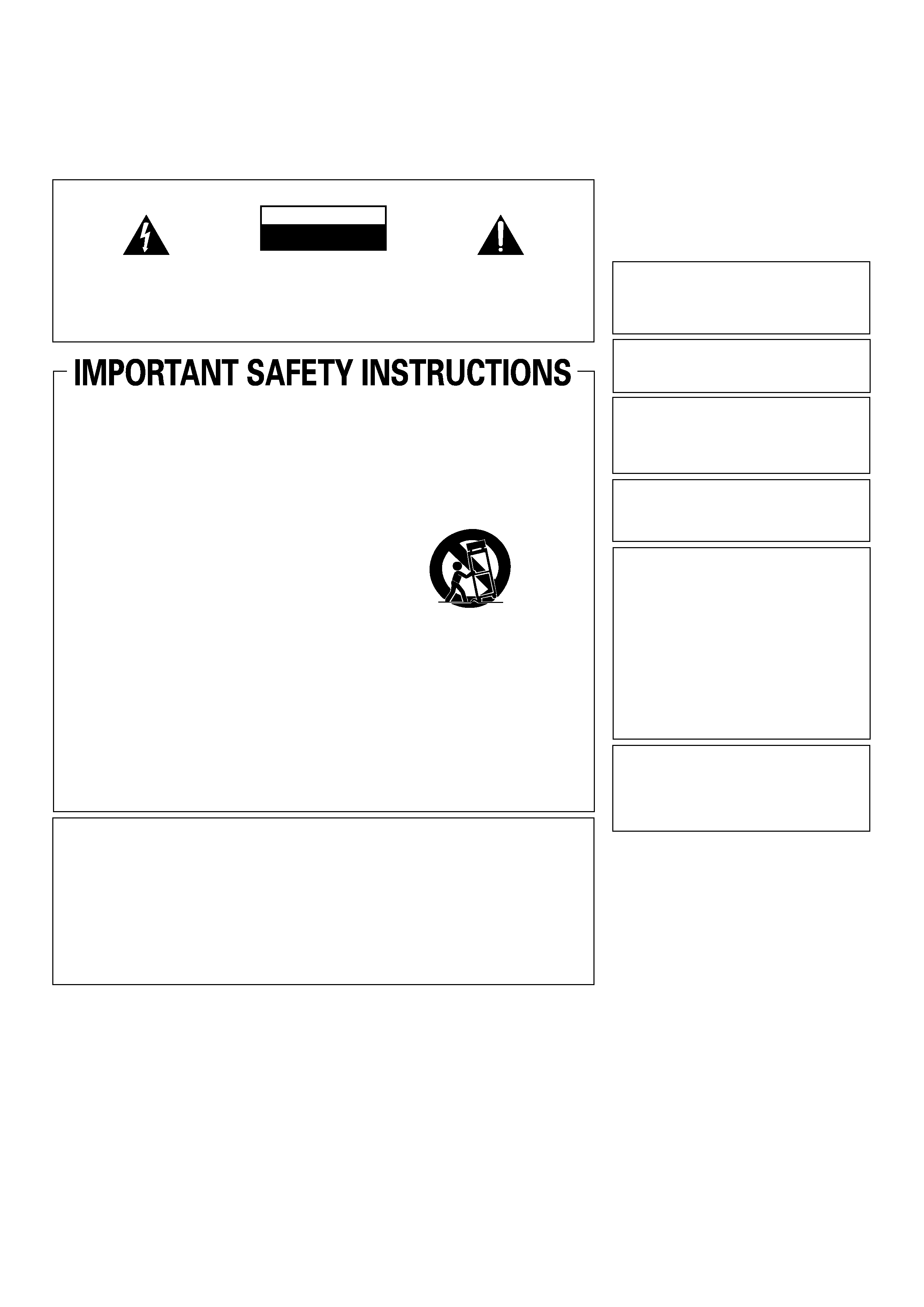
The exclamation point within an equilateral
triangle is intended to alert the user to the
presence of important operating and
maintenance (servicing) instructions in the
literature accompanying the appliance.
The lightning flash with arrowhead symbol,
within an equilateral triangle, is intended to
alert the user to the presence of uninsulated
"dangerous voltage" within the product's
enclosure that may be of sufficient
magnitude to constitute a risk of electric
shock to persons.
CAUTION:
TO PREVENT THE RISK OF ELECTRIC
SHOCK, DO NOT REMOVE COVER (OR
BACK). NO USER-SERVICEABLE PARTS
INSIDE. REFER SERVICING TO QUALIFIED
SERVICE PERSONNEL.
CAUTION
RISK OF ELECTRIC SHOCK
DO NOT OPEN
IMPORTANT
D1-4-2-3_En-A
Read these instructions.
Keep these instructions.
Heed all warnings.
Follow all instructions.
Do not use this apparatus near water.
Clean only with dry cloth.
Do not block any ventilation openings.
Install in accordance with the
manufacturer's instructions.
Do not install near any heat sources such
as radiators, heat registers, stoves,
or other apparatus (including amplifiers)
that produce heat.
Do not defeat the safety purpose of the
polarized or grounding-type plug.
A polarized plug has two blades with one
wider than the other. A grounding type
plug has two blades and a third grounding
prong. The wide blade or the third prong
are provided for your safety. If the provided
plug does not fit into your outlet, consult
an electrician for replacement of the
obsolete outlet.
Protect the power cord from being walked
on or pinched particularly at plugs,
convenience receptacles, and the point
where they exit from the apparatus.
1)
2)
3)
4)
5)
6)
7)
8)
9)
10)
Only use attachments/accessories
specified by the manufacturer.
Use only with the cart, stand, tripod,
bracket, or table specified by the
manufacturer, or sold with the apparatus.
When a cart is used, use caution when
moving the cart/apparatus combination to
avoid injury from tip-over.
Unplug this apparatus during lightning
storms or when unused for long periods of
time.
Refer all servicing to qualified service
personnel. Servicing is required when the
apparatus has been damaged in any way,
such as power-supply cord or plug is
damaged, liquid has been spilled or
objects have fallen into the apparatus, the
apparatus has been exposed to rain or
moisture, does not operate normally, or
has been dropped.
P1-4-2-2_En
11)
12)
13)
14)
NOTE: This equipment has been tested and found to comply with the limits for a Class B digital device, pursuant to
Part 15 of the FCC Rules. These limits are designed to provide reasonable protection against harmful interference in
a residential installation. This equipment generates, uses, and can radiate radio frequency energy and, if not
installed and used in accordance with the instructions, may cause harmful interference to radio communications.
However, there is no guarantee that interference will not occur in a particular installation. If this equipment does
cause harmful interference to radio or television reception, which can be determined by turning the equipment off
and on, the user is encouraged to try to correct the interference by one or more of the following measures:
­ Reorient or relocate the receiving antenna.
­ Increase the separation between the equipment and receiver.
­ Connect the equipment into an outlet on a circuit different from that to which the receiver is connected.
­ Consult the dealer or an experienced radio/TV technician for help.
D8-10-1-2_En
Thank you for buying this Pioneer product.
Please read through these operating instructions so you will know how to operate your model properly. After you have finished reading
the instructions, put them away in a safe place for future reference.
In some countries or regions, the shape of the power plug and power outlet may sometimes differ from that shown in the explanatory
drawings. However the method of connecting and operating the unit is the same.
K015 En
WARNING
This equipment is not waterproof. To prevent a fire
or shock hazard, do not place any container filed
with liquid near this equipment (such as a vase or
flower pot) or expose it to dripping, splashing, rain
or moisture.
D3-4-2-1-3_A_En
IMPORTANT NOTICE ­ THE SERIAL NUMBER FOR
THIS EQUIPMENT IS LOCATED IN THE REAR.
PLEASE WRITE THIS SERIAL NUMBER ON YOUR
ENCLOSED WARRANTY CARD AND KEEP IN A
SECURE AREA. THIS IS FOR YOUR SECURITY.
D1-4-2-6-1_En
This Class B digital apparatus complies with
Canadian ICES-003.
Cet appareil numérique de la Classe B est conforme
à la norme NMB-003 du Canada.
D8-10-1-3_EF
Information to User
Alteration or modifications carried out without
appropriate authorization may invalidate the user's
right to operate the equipment.
D8-10-2_En
CAUTION: This product satisfies FCC regulations
when shielded cables and connectors are used to
connect the unit to other equipment. To prevent
electromagnetic interference with electric appliances
such as radios and televisions, use shielded cables
and connectors for connections.
D8-10-3a_En
CAUTION
­ PREVENT ELECTRIC SHOCK DO
NOT USE THIS (POLARIZED) PLUG
WITH AN EXTENSION CORD.
RECEPTACLE OR OTHER OUTLET
UNLESS THE BLADES CAN BE
FULLY INSERTED TO PREVENT
BLADE EXPOSURE.
ATTENTION ­ POUR PREVENIR LES CHOCS
ELECTRIQUES NE PAS UTILISER
CETTE FICHE POLARISEE AVEC UN
PROLONGATEUR UNE PRISE DE
COURANT OU UNE AUTRE SORTIE
DE COURANT, SAUF SI LES LAMES
PEUVENT ETRE INSEREES A FOND
SANS EN LAISSER AUCUNE PARTIE
A DECOUVVERT.
D2-4-4-1_EF
WARNING: Handling the cord on this product or
cords associated with accessories sold with the
product will expose you to chemicals listed on
proposition 65 known to the State of California and
other governmental entities to cause cancer and
birth defect or other reproductive harm.
Wash hands after handling
D36-P4_A_En
WARNING
To prevent a fire hazard, do not place any naked
flame sources (such as a lighted candle) on the
equipment.
D3-4-2-1-7a_A_En
VENTILATION CAUTION
When installing this unit, make sure to leave space
around the unit for ventilation to improve heat
radiation (at least 5 cm at rear, and 3 cm at each
side).
WARNING
Slots and openings in the cabinet are provided for
ventilation to ensure reliable operation of the
product, and to protect it from overheating. To
prevent fire hazard, the openings should never be
blocked or covered with items (such as newspapers,
table-cloths, curtains) or by operating the
equipment on thick carpet or a bed.
D3-4-2-1-7b_A_En
POWER-CORD CAUTION
Handle the power cord by the plug. Do not pull out the
plug by tugging the cord and never touch the power
cord when your hands are wet as this could cause a
short circuit or electric shock. Do not place the unit, a
piece of furniture, etc., on the power cord, or pinch the
cord. Never make a knot in the cord or tie it with other
cords. The power cords should be routed such that they
are not likely to be stepped on. A damaged power cord
can cause a fire or give you an electrical shock. Check
the power cord once in a while. When you find it
damaged, ask your nearest PIONEER authorized
service center or your dealer for a replacement.
S002_En
background image
3
Location
Install the unit in a well-ventilated location where it will not
be exposed to high temperatures or humidity.
÷ Do not install the unit in a location which is exposed to
direct rays of the sun, or near stoves or radiators. Excessive
heat can adversely affect the cabinet and internal
components. Installation of the unit in a damp or dusty
environment may also result in a malfunction or accident.
(Avoid installation near cookers etc., where the unit may be
exposed to oily smoke, steam or heat.)
÷ When the unit is used inside a carrying case or DJ booth,
separate it from the walls or other equipment to improve
heat radiation.
CAUTIONS REGARDING HANDLING
Cleaning the Unit
÷ Use a polishing cloth to wipe off dust and dirt.
÷ When the surfaces are very dirty, wipe with a soft cloth
dipped in some neutral cleanser diluted five or six times
with water and wrung out well, then wipe again with a dry
cloth. Do not use furniture wax or cleaners.
÷ Never use thinners, benzene, insecticide sprays or other
chemicals on or near this unit, since these will corrode the
surfaces.
S001_En
Selecting fine audio equipment such as the unit
you've just purchased is only the start of your
musical enjoyment. Now it's time to consider how
you can maximize the fun and excitement your
equipment offers. This manufacturer and the
Electronic Industries Association's Consumer
Electronics Group want you to get the most out of
your equipment by playing it at a safe level. One that
lets the sound come through loud and clear without
annoying blaring or distortion-and, most importantly,
without affecting your sensitive hearing.
Sound can be deceiving. Over time your hearing
"comfort level" adapts to higher volumes of sound.
So what sounds "normal" can actually be loud and
harmful to your hearing. Guard against this by
setting your equipment at a safe level BEFORE your
hearing adapts.
To establish a safe level:
· Start your volume control at a low setting.
· Slowly increase the sound until you can hear it
comfortably and clearly, and without distortion.
Once you have established a comfortable sound
level:
· Set the dial and leave it there.
Taking a minute to do this now will help to prevent
hearing damage or loss in the future. After all, we
want you listening for a lifetime.
We Want You Listening For A Lifetime
Used wisely, your new sound equipment will
provide a lifetime of fun and enjoyment. Since
hearing damage from loud noise is often
undetectable until it is too late, this manufacturer
and the Electronic Industries Association's
Consumer Electronics Group recommend you avoid
prolonged exposure to excessive noise. This list of
sound levels is included for your protection.
Decibel
Level Example
30
Quiet library, soft whispers
40
Living room, refrigerator, bedroom away from traffic
50
Light traffic, normal conversation, quiet office
60
Air conditioner at 20 feet, sewing machine
70
Vacuum cleaner, hair dryer, noisy restaurant
80
Average city traffic, garbage disposals, alarm clock
at two feet.
THE FOLLOWING NOISES CAN BE DANGEROUS
UNDER CONSTANT EXPOSURE
90
Subway, motorcycle, truck traffic, lawn mower
100
Garbage truck, chain saw, pneumatic drill
120
Rock band concert in front of speakers,
thunderclap
140
Gunshot blast, jet plane
180
Rocket launching pad
Information courtesy of the Deafness Research Foundation.
background image
4
FEATURES
CONTENTS
CONFIRM ACCESSORIES
1 Designed for high sound quality
Analog signals are transmitted by the shortest circuitry and
converted to digital format at 96 kHz sampling rate via a 24-bit high
quality A/D converter. As a result, signals are passed to the digital
mixing stage in the best possible state. Mixing is performed with a
32-bit DSP, totally eliminating any loss in fidelity, while the ideal level
of filtering is introduced to produce optimum sound for DJ play.
These features are housed in a high-rigidity chassis with double-
shielded construction together with a high-performance power
section and other features of the high-fidelity technology also used in
the DJM-1000, thus guaranteeing the utmost in clear and powerful
club sounds.
2 Sound-color effects
1) Harmonic effect
Equipped with the industry's first "harmonic effect" function that
detects the track's key and provides optimum tuning for DJ play.
This new function allows smoother, more natural DJ mixing
compared to earlier models which allowed DJ play with track tempo
adjustment alone.
2) Modulation effect
"Filter," "crush," and "sweep" effects have been added to each
channel.
These allow a greater breadth to DJ play by permitting the user to
apply effects more intuitively.
Also, by combining these with "beat effects," some 50 kinds of effect
can be produced, giving the user a vast potential for remix and DJ
play.
3 Beat effects
The "beat effects" so popular on the DJM-600 are continued here.
Effects can be applied in linkage to the BPM (Beats Per Minute) count,
thus allowing the production of a variety of sounds.
Some of the effects include delay, echo, reverse delay, pan, trance,
filter, flanger, phaser, reverb, robot, chorus, roll, and reverse roll.
4 Digital IN/OUT
The digital input connectors support each of the sampling rates (44.1/
48/96 kHz), thus allowing the connection of digital components for a
DJ system with no sound degradation.
Likewise the digital output connectors support sampling rates 96 kHz/
24-bit and 48 kHz/24-bit, making the unit even more convenient for
cutting studio tracks or on other occasions when high sound fidelity
is required. (Only linear PCM is supported.)
5 MIDI OUT
Virtually all the dial and switch information of the DJM-800 can be
output in MIDI signal format, allowing external components to be
controlled via MIDI.
6 Other functions
¶ A control cable can be used to connect the unit to a Pioneer DJ CD
player, thus allowing playback to be linked to operation of the
fader ("fader start play").
¶ Built-in "3-band equalizer" supports level control within the range
of +6 dB to ­26 dB in each bandwidth.
¶ "Cross fader assignment" function allows each channel's input to
be assigned flexibly to a cross fader.
¶ "Talk over" function automatically lowers track volume during
microphone input.
¶ "Fader curve adjustment" function allows modification of the
cross fader and channel fader curves.
¶ "Microphone cut" function mutes microphone output to the
booth monitor, thus preventing uncomfortable feedback.
¶ By replacing the channel fader section with the optional rotary
volume kit DJC-800RV, the slider control can be replayed with a
rotary type control.
CAUTIONS REGARDING HANDLING ........................ 3
CONFIRM ACCESSORIES ........................................... 4
FEATURES ................................................................... 4
BEFORE USING
CONNECTIONS ............................................................ 5
CONNECTION PANEL ........................................... 5
CONNECTING INPUTS .......................................... 6
CONNECTING EXTERNAL EFFECTORS,
OUTPUT CONNECTORS ....................................... 7
ABOUT MIDI CONNECTORS ................................ 7
CONNECTING MICROPHONE AND
HEADPHONES ........................................................ 8
CONNECTING THE POWER CORD ...................... 8
NAMES AND FUNCTIONS OF PARTS ...................... 9
OPERATION PANEL ............................................... 9
DISPLAY SECTION .............................................. 12
OPERATIONS
MIXER OPERATIONS ................................................ 13
BASIC OPERATIONS ........................................... 13
FADER START FUNCTION .................................. 14
EFFECT FUNCTIONS ................................................. 15
TYPES OF BEAT EFFECTS .................................. 15
PRODUCING BEAT EFFECTS .............................. 17
TYPE OF SOUND-COLOR EFFECT ..................... 18
USING SOUND-COLOR EFFECTS ...................... 18
EFFECT PARAMETERS ........................................ 19
MIDI SETTINGS ......................................................... 20
SYNCHRONIZING AUDIO SIGNALS TO
EXTERNAL SEQUENCER, OR USING
DJM-800 INFORMATION TO OPERATE
AN EXTERNAL SEQUENCER .............................. 20
MIDI MESSAGES ................................................. 20
PROGRAM CHANGE ........................................... 21
SNAPSHOT ........................................................... 21
OTHER
TROUBLESHOOTING ................................................ 22
SPECIFICATIONS ....................................................... 23
BLOCK DIAGRAM ...................................................... 24
Operating Instructions ........................................................... 1
Power cord ............................................................................. 1
Warranty ................................................................................. 1
background image
5
CONNECTION PANEL
1. POWER switch
2. MASTER 2 output connectors
RCA type unbalanced output.
3. Recording output connectors (REC)
RCA type output connectors for recording.
4. PHONO input connectors
RCA type phono level (MM cartridge) input connectors.
Do not use for inputting line level signals.
5. LINE input connectors
RCA type line level input connectors.
Use to connect a cassette deck or other line level output component.
6. Signal grounding terminals (SIGNAL GND)
Use to connect ground wires from analog players.
This is not a safety grounding terminal.
7. CD input connectors
RCA type line level input connectors.
Use to connect a DJ CD player or other line level output component.
8. DIGITAL IN connectors
RCA type digital coaxial input connectors.
Use to connect to DJ CD player or other digital coaxial output
connectors.
9. MIDI OUT connector
DIN type output connector.
Use to connect to other MIDI component (see P. 20).
10. DIGITAL OUT connector
RCA type digital coaxial output connector.
Master audio digital output.
11. Sampling frequency selector switch (fs 48 k/96 k)
Use to set the sampling frequency of the digital output to 96 kHz/24-
bit or 48 kHz/24-bit.
12. DIGITAL/CD input selector switches
Use to select either analog input (CD) or digital input (DIGITAL IN).
13. RETURN connectors
Ø6.3 mm phone-type input connectors.
Use to connect to the output connectors of external effectors or
similar components.
When the L channel only is connected, the L channel input is
simultaneously input to the R channel.
14. SEND output connectors
Ø6.3 mm phone-type output connectors.
Use to connect to the input connectors of external effectors or other
similar components. When the L channel only is connected, a L+R
monaural signal is output.
15. CONTROL connectors
Ø3.5 mm mini-connector. Use to connect to the control connector of
a Pioneer DJ CD player.
When the connectors are connected, the DJM-800's fader can be
used to perform start/stop on the DJ CD player.
16. BOOTH monitor output connectors
Ø6.3 mm phone-type booth monitor output connectors.
The sound level from these connectors is controlled independently
by the BOOTH MONITOR level dial, regardless of the position of the
MASTER LEVEL dial. (These connectors are TRS output, so they
support both balanced and unbalanced outputs.)
17. DIGITAL/LINE input selector switches
Use to select either analog input (LINE) or digital input (DIGITAL IN).
18. Master output attenuator switch (MASTER ATT)
Use to attenuate the level of the master 1 and master 2 outputs.
Selectable values are 0 dB, ­3 dB, ­6 dB and ­12 dB.
19. Microphone signal switch
(MIC SIGNAL ADD/CUT)
When set to the [ADD] position, the sounds from microphone 1 and
microphone 2 are output to the BOOTH monitor output connectors.
When set to the [CUT] position, the sounds from microphone 1 and
microphone 2 are not output to the BOOTH monitor output
connectors.
20. MASTER 1 output connectors
XLR type (male) balanced output.
÷ When using a cord with RCA-type plug, users are recommended
to connect the plug directly to the MASTER 2 connectors without
using an XLR/RCA converter plug.
21. Power inlet (AC IN)
Use the accessory power cord to connect to an AC power outlet of the
proper voltage.
CONNECTIONS
POWER
MASTER 2
REC
RL
R
(TRS)
L
MASTER 1
L
R
PHONO
CONTROL
DIGITAL
MIC SIGNAL
CUT
ADD
SIGNAL GND
SIGNAL GND
LINE
DIGITAL
LINE
DIGITAL
CD
DIGITAL
CD
LINE
L
R
AC IN
OFF
ON
1GND
3COLD
MASTER ATT
2HOT
PHONO
CONTROL
BOOTH
R
L(MONO)
SEND
R
L(MONO)
RETURN
LINE
L
R
PHONO
CONTROL
CD
L
R
LINE
CONTROL
DIGITAL OUT
MIDI OUT
fs (Hz)
48 k
96 k
CD
L
R
-12dB
-6dB
-3dB
0dB
DIGITAL IN
1
2
3
4
5
6
8
9
10
11
13
12
14
15
16
17
18
19
20
21
7
CONNECTIONS (CONNECTION PANEL)

Reviews

There are no reviews of this manual yet.