PIONEER CORPORATION
4-1, Meguro 1-Chome, Meguro-ku, Tokyo 153-8654, Japan
PIONEER ELECTRONICS (USA) INC.
P.O.Box 1760, Long Beach, CA 90801-1760 U.S.A.
PIONEER EUROPE NV
Haven 1087 Keetberglaan 1, 9120 Melsele, Belgium
PIONEER ELECTRONICS ASIACENTRE PTE.LTD. 253 Alexandra Road, #04-01, Singapore 159936
C PIONEER CORPORATION 2001
K-ZZS. AUG. 2001 Printed in Japan
ORDER NO.
CRT2752
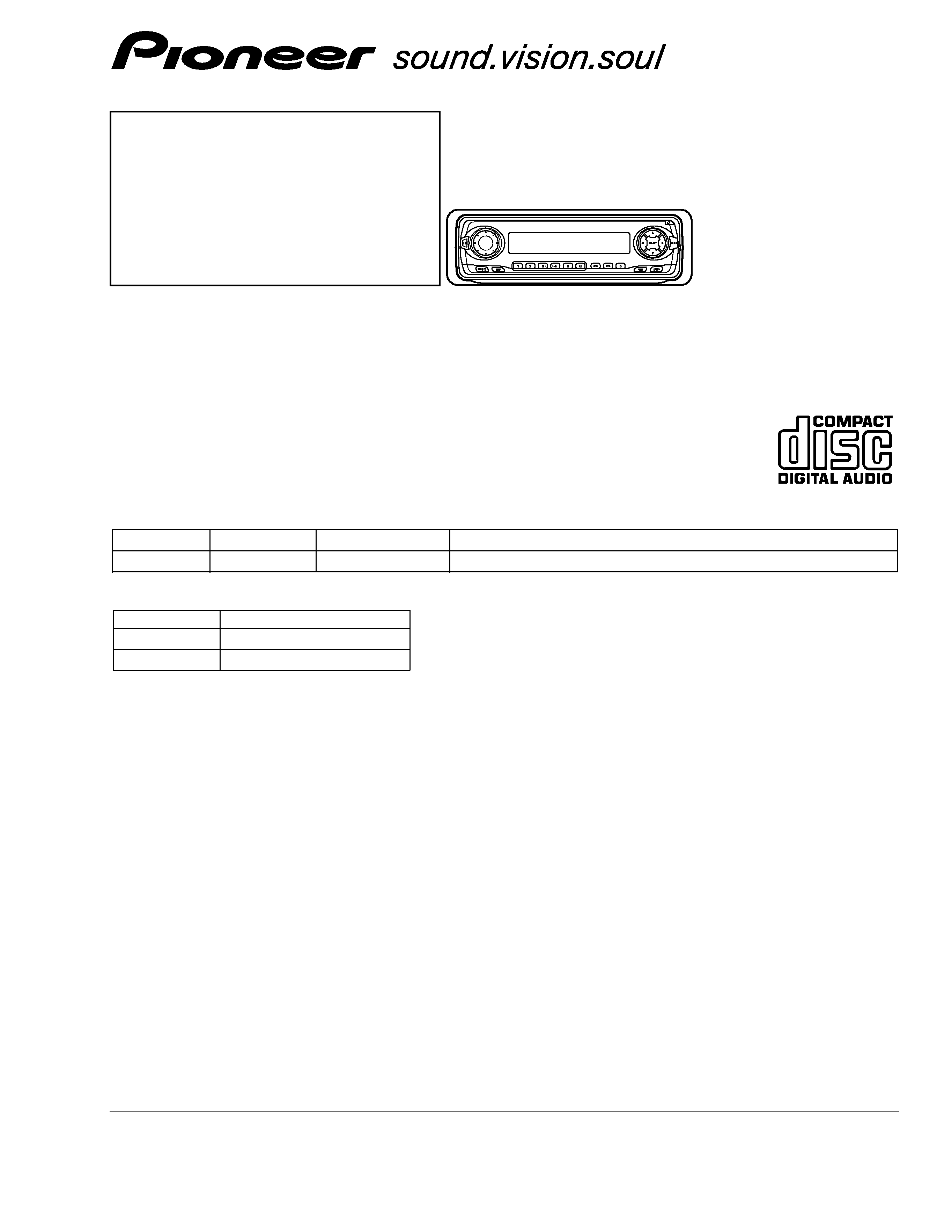
MULTI-CD CONTROL HIGH POWER CD PLAYER WITH XM/FM/AM TUNER
DEH-P3370XM
UC
Service
Manual
- This service manual should be used together with the following manual(s):
Model No.
Order No.
Mech. Module
Remarks
CX-977
CRT2624
S9
CD Mech. Module:Circuit Description, Mech. Description, Disassembly
CONTENTS
1. SAFETY INFORMATION ............................................2
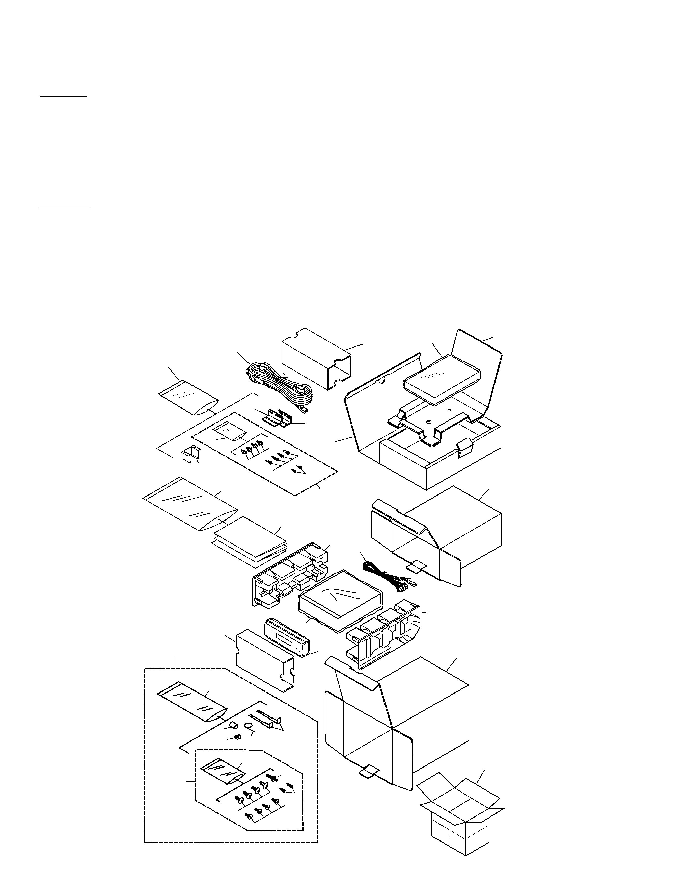
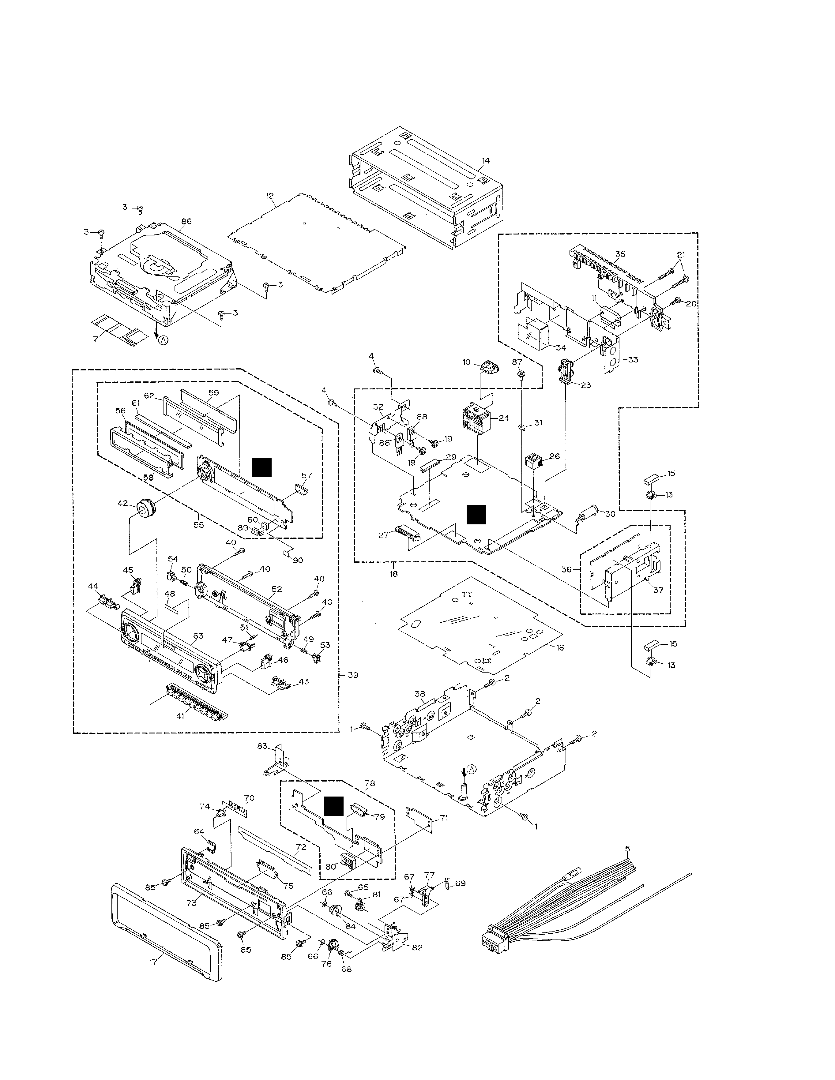
2. EXPLODED VIEWS AND PARTS LIST .......................2
3. BLOCK DIAGRAM AND SCHEMATIC DIAGRAM ...10
4. PCB CONNECTION DIAGRAM ................................40
5. ELECTRICAL PARTS LIST ........................................56
6. ADJUSTMENT..........................................................66
7. GENERAL INFORMATION .......................................85
7.1 DIAGNOSIS ........................................................85
7.1.1 DISASSEMBLY .........................................85
7.1.2 CONNECTOR FUNCTION DESCRIPTION ...89
7.2 PARTS .................................................................90
7.2.1 IC................................................................90
7.2.2 DISPLAY ..................................................107
7.3 OPERATIONAL FLOW CHART .........................108
8. OPERATIONS AND SPECIFICATIONS...................109
- CD Player Service Precautions
1. For pickup unit(CXX1480) handling, please refer
to"Disassembly"(see page 85).
During replacement, handling precautions shall be
taken to prevent an electrostatic discharge(protection
by a jumper-solder).
2. During disassembly, be sure to turn the power off
since an internal IC might be destroyed when a con-
nector is plugged or unplugged.
3. Please checking the grating after changing the ser-
vice pickup unit(see page 68).
- This product has the unit part numbers as below.
Unit Part No.
Description
CPN1760
CD Player
CPN1761
XM Tuner
*) The unit part numbers listed above are not for the service components.