PIONEER DEH-P2530RXN Service Manual

Cover page of PIONEER DEH-P2530RXN Service Manual

Service Manual for PIONEER DEH-P2530RXN, downloadable as a PDF file.

Manual details

  • Immediate download after payment.
  • Delivered as a PDF file.
  • The manual has 64 pages
  • File size: 4.32 MB
  • Available language versions: English
  • Different language versions may vary sligthly in file size and page count.

We guarantee that...

  • our manuals are complete,
  • the manual includes circuit diagrams,
  • our manuals are checked with antivirus,
  • We'll issue refund if the manual is damaged, incomplete or unreadable (our refund policy)

Sample pages

Thumbnail of page 1Thumbnail of page 2Thumbnail of page 3Thumbnail of page 4
Thumbnail of page 5Thumbnail of page 6Thumbnail of page 7Thumbnail of page 8
Thumbnail of page 9
background image
PIONEER CORPORATION
4-1, Meguro 1-Chome, Meguro-ku, Tokyo 153-8654, Japan
PIONEER ELECTRONICS (USA) INC.
P.O.Box 1760, Long Beach, CA 90801-1760 U.S.A.
PIONEER EUROPE NV
Haven 1087 Keetberglaan 1, 9120 Melsele, Belgium
PIONEER ELECTRONICS ASIACENTRE PTE.LTD. 253 Alexandra Road, #04-01, Singapore 159936
C PIONEER CORPORATION 2002
K-ZZA. OCT. 2002 Printed in Japan
ORDER NO.
CRT2982
MULTI-CD CONTROL HIGH POWER CD PLAYER WITH RDS TUNER
DEH-P2530R
XM/EW, XN/EW
Service
Manual
DEH-P2530R/XM/EW
- This service manual should be used together with the following manual(s):
Model No.
Order No.
Mech. Module Remarks
CX-3026
CRT2944
S10
CD Mech. Module:Circuit Description, Mech.Description, Disassembly
DEH-P2500R XM/EW, XN/EW
For details, refer to "Important symbols for good services".
DEH-P2500RB XM/EW, XN/EW
background image
2
This service manual is intended for qualified service technicians; it is not meant for the casual do-it-yourselfer.
Qualified technicians have the necessary test equipment and tools, and have been trained to properly and safely
repair complex products such as those covered by this manual.
Improperly performed repairs can adversely affect the safety and reliability of the product and may void the warranty.
If you are not qualified to perform the repair of this product properly and safely, you should not risk trying to do so
and refer the repair to a qualified service technician.
1. Safety Precautions for those who Service this Unit.
· When checking or adjusting the emitting power of the laser diode exercise caution in order to get safe, reliable
results.
Caution:
1. During repair or tests, minimum distance of 13cm from the focus lens must be kept.
2. During repair or tests, do not view laser beam for 10 seconds or longer.
2. A "CLASS 1 LASER PRODUCT" label is affixed to the
bottom of the player.
3. The triangular label is attached to the mechanism
unit frame.
4. Specifications of Laser Diode
Specifications of laser radiation fields to which human access is possible during service.
Wavelength = 800 nanometers
CLASS 1
LASER PRODUCT
1
234
12
34
F
E
D
C
B
A
DEH-P2530R/XM/EW
SAFETY INFORMATION
background image
3
5
6
7
8
F
E
D
C
B
A
5
6
7
8
DEH-P2530R/XM/EW
[ Important symbols for good services ]
In this manual, the symbols shown-below indicate that adjustments, settings or cleaning should be made securely.
When you find the procedures bearing any of the symbols, be sure to fulfill them:
2. Adjustments
To keep the original performances of the product, optimum adjustments or specification confirmation is indispensable.
In accordance with the procedures or instructions described in this manual, adjustments should be performed.
3. Cleaning
For optical pickups, tape-deck heads, lenses and mirrors used in projection monitors, and other parts requiring cleaning,
proper cleaning should be performed to restore their performances.
5. Lubricants, glues, and replacement parts
Appropriately applying grease or glue can maintain the product performances. But improper lubrication or applying
glue may lead to failures or troubles in the product. By following the instructions in this manual, be sure to apply the
prescribed grease or glue to proper portions by the appropriate amount.For replacement parts or tools, the prescribed
ones should be used.
4. Shipping mode and shipping screws
To protect the product from damages or failures that may be caused during transit, the shipping mode should be set or
the shipping screws should be installed before shipping out in accordance with this manual, if necessary.
1. Product safety
You should conform to the regulations governing the product (safety, radio and noise, and other regulations), and
should keep the safety during servicing by following the safety instructions described in this manual.
background image
4
1
234
12
34
F
E
D
C
B
A
DEH-P2530R/XM/EW
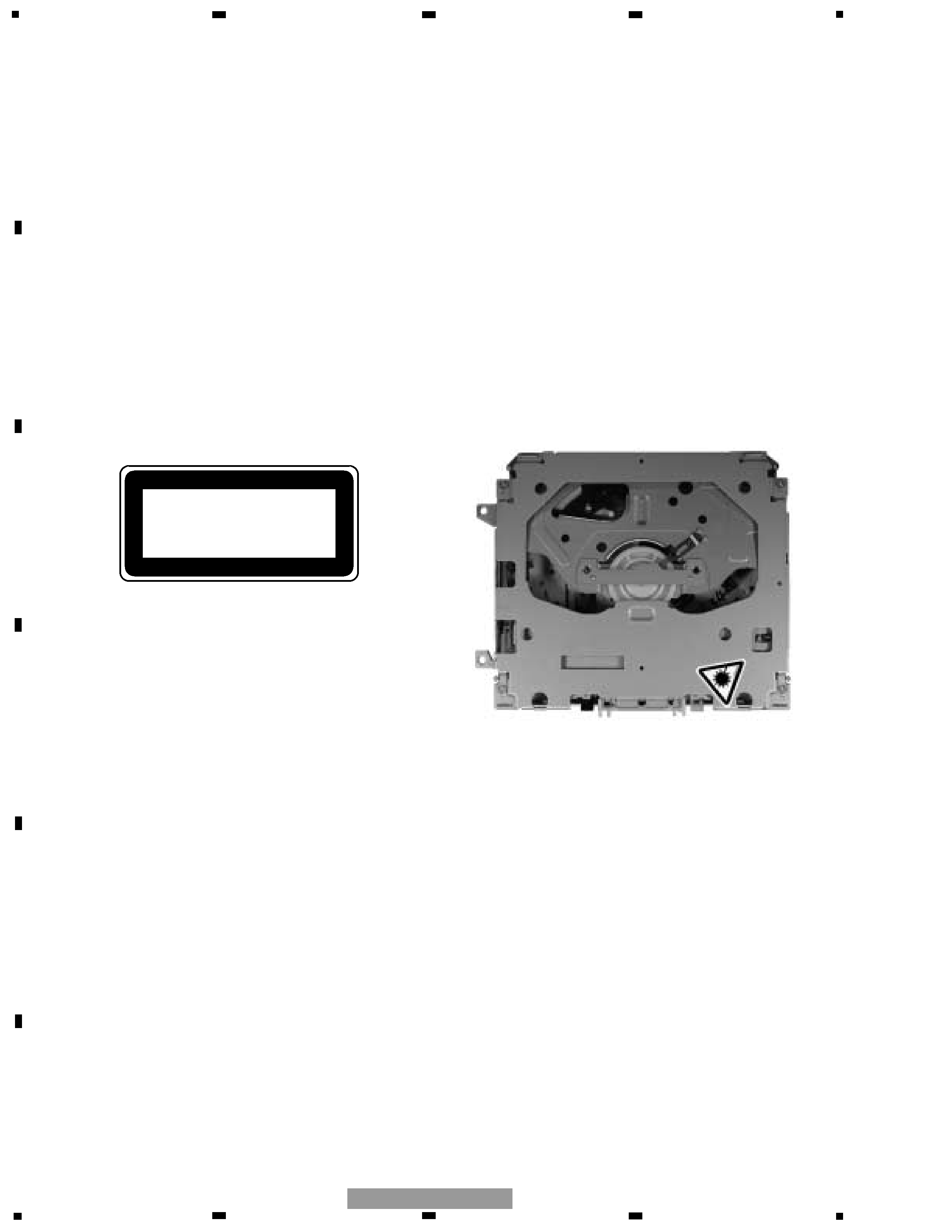
- CD Player Service Precautions
1. Before disassembling the unit, be sure to turn off the
power. Unplugging and plugging the connectors dur-
ing power-on mode may damage the ICs inside the
unit.
2. To protect the pickup unit from electrostatic dis-
charge during serviving, take an appropriate treat-
ment(shorting-solder) by referring to "the DISAS-
SEMBLY" on page 45.
3. After replacing the pickup unit, be sure to check the
grating.(See p.42.)
CONTENTS
SAFETY INFORMATION ............................................................................................................................................2
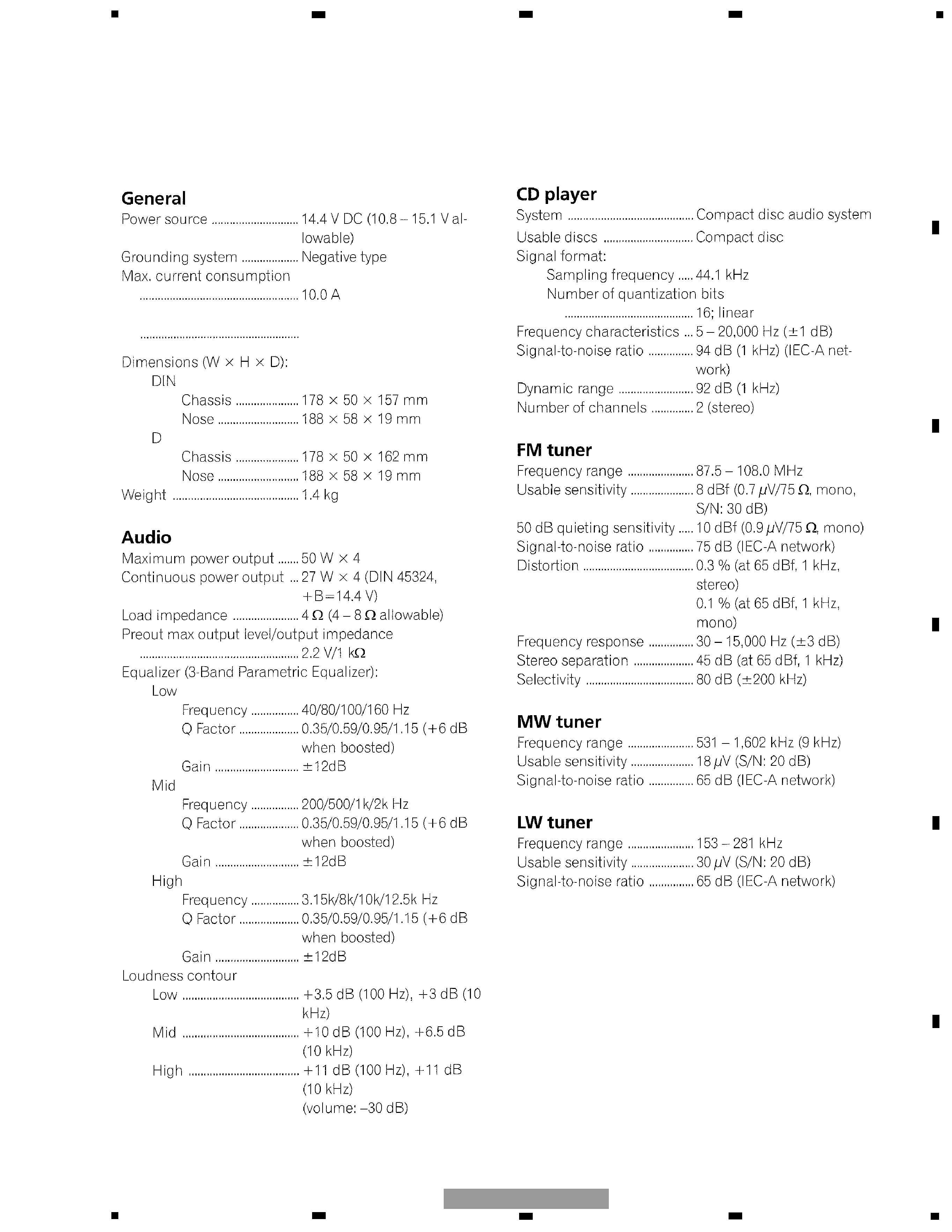
1. SPECIFICATIONS .......................................................................................................................................................5
2. EXPLODED VIEWS AND PARTS LIST.......................................................................................................................6
2.1 PACKING...............................................................................................................................................................6
2.2 EXTERIOR.............................................................................................................................................................8
2.3 CD MECHANISM MODULE ...............................................................................................................................12
3. BLOCK DIAGRAM AND SCHEMATIC DIAGRAM ...................................................................................................14
3.1 BLOCK DIAGRAM ..............................................................................................................................................14
3.2 OVERALL CONNECTION DIAGRAM(GUIDE PAGE) ........................................................................................16
3.3 KEYBOARD UNIT ...............................................................................................................................................22
3.4 CD MECHANISM MODULE ...............................................................................................................................24
4. PCB CONNECTION DIAGRAM ................................................................................................................................28
4.1 TUNER AMP UNIT .............................................................................................................................................28
4.2 PANEL UNIT .......................................................................................................................................................32
4.3 KEYBOARD UNIT ...............................................................................................................................................33
4.4 CD MECHANISM MODULE ...............................................................................................................................34
5. ELECTRICAL PARTS LIST ........................................................................................................................................36
6. ADJUSTMENT .........................................................................................................................................................40
6.1 CD ADJUSTMENT .............................................................................................................................................40
6.2 CHECKING THE GRATING AFTER CHANGING THE PICKUP UNIT................................................................42
6.3 ERROR MODE ....................................................................................................................................................44
7. GENERAL INFORMATION .......................................................................................................................................45
7.1 DIAGNOSIS ........................................................................................................................................................45
7.1.1 DISASSEMBLY ..............................................................................................................................................45
7.1.2 CONNECTOR FUNCTION DESCRIPTION ....................................................................................................47
7.2 PARTS .................................................................................................................................................................48
7.2.1 IC ....................................................................................................................................................................48
7.2.2 DISPLAY.........................................................................................................................................................56
7.3 OPERATIONAL FLOW CHART...........................................................................................................................58
7.4 CLEANING ..........................................................................................................................................................59
8. OPERATIONS ...........................................................................................................................................................60
background image
5
Backup current
5 mA or less
5
6
7
8
F
E
D
C
B
A
5
6
7
8
DEH-P2530R/XM/EW
1. SPECIFICATIONS

Reviews

There are no reviews of this manual yet.