PIONEER CX-3016 Service Manual

Cover page of PIONEER CX-3016 Service Manual

Service Manual for PIONEER CX-3016, downloadable as a PDF file.

Manual details

  • Immediate download after payment.
  • Delivered as a PDF file.
  • The manual has 28 pages
  • File size: 0.94 MB
  • Available language versions: English
  • Different language versions may vary sligthly in file size and page count.

We guarantee that...

  • our manuals are complete,
  • the manual includes circuit diagrams,
  • our manuals are checked with antivirus,
  • We'll issue refund if the manual is damaged, incomplete or unreadable (our refund policy)

Sample pages

Thumbnail of page 1Thumbnail of page 2Thumbnail of page 3Thumbnail of page 4
Thumbnail of page 5Thumbnail of page 6Thumbnail of page 7Thumbnail of page 8
Thumbnail of page 9
background image
Model
Service Manual
DVD Mechanism Module
AVH-P6500DVD/UC
CRT3038
CXK6310
DVH-P5000MP/UC
CRT3074
CXK6312
AVH-P7500DVD/UC
CRT3039
CXK6300
PIONEER CORPORATION
4-1, Meguro 1-Chome, Meguro-ku, Tokyo 153-8654, Japan
PIONEER ELECTRONICS SERVICE INC.
P.O.Box 1760, Long Beach, CA 90801-1760 U.S.A.
PIONEER EUROPE NV
Haven 1087 Keetberglaan 1, 9120 Melsele, Belgium
PIONEER ELECTRONICS ASIACENTRE PTE.LTD. 253 Alexandra Road, #04-01, Singapore 159936
C PIONEER CORPORATION 2003
K-ZZU. APR. 2003 Printed in Japan
ORDER NO.
CRT3056
DVD MECHANISM MODULE(MS3)
CX-3016
- This service manual describes the operation of the DVD mechanism modules incorporated in the
models listed below.
- When performing repairs use this manual together with the specific manual for the model under repair.
- The DVD mechanism MS3 has VIDEO-type and ROM-type models. This manual covers the operations
for both models.
CONTENTS
1. CIRCUIT DESCRIPTIONS ...........................................2
2. MECHANISM DESCRIPTIONS.................................15
3. DISASSEMBLY .........................................................20
Service
Manual
background image
2
1
234
12
34
CX-3016
F
E
D
C
B
A
1.1.1 APC circuit
The light output of laser diodes (LD) has largely negative thermal characteristics. If they are driven with a constant
current, the laser power level will not be constant. The APC circuit is designed to control the current so that the laser
power becomes constant through the monitor diode (MD). The IC AN8703FH contains two APC circuits, one for DVDs
and the other for CDs. The LD current values for DVDs can be calculated by dividing the voltage between the DVDLD1
(or CDLD1 for CDs) and 5V line by 15.6 ohms (3.9 ohms x 4): approximately 26mA and 44mA for DVDs and CDs
respectively.
180mV
LPC01
LPC1
AN8703FH
For DVD
PU UNIT
2
1
+
+
+5V
DVDLD0
DVDLD1
26
DVD
LD
+5V
MD
65LD
65MD
7
3.9
3.9 3.9 3.9
­
+
170mV
LPC02
LPC2
For CD
4
3
+
+5V
CDLD0
CDLD1
24
CD
LD
78LD
CN1101
78MD
5
3.9
3.9 3.9 3.9
­
+
1.Circuit descriptions
1.1 Front-end processor (FEP) section (AN8703FH: IC1101)
The IC1101 generates servo signals for focus and tracking operations, processes the RF signal, and controls the laser
power of the pickup.
For servo signal processing, the IC contains a focus operational amplifier, a focus balance adjustment circuit, a three-
beam tracking operational amplifier, a phase-difference tracking detection circuit, a tracking balance adjustment circuit,
and an envelope detection circuit.
For the RF signal processing, the AGC and equalizer functions are contained in the IC.
background image
3
5
6
7
8
5
6
7
8
CX-3016
F
E
D
C
B
A
1.1.2 Focus error (FE) generating circuit
Focus error (FE) generating circuit
The signals B1 through B4, obtained by dividing the output in the pickup, are applied to the FE generating circuit.
Inside the circuit, the (B1 + B3) and (B2 + B4) signals are generated via the internal resistors, fed into the variable
amplifier for the focus balance adjustment, and finally the FE signal is generated by amplifying the {(B1 + B3) ­ (B2 +
B4)} signal.
The pin numbers and names in the brackets are for CDs. The circuits for CDs and DVDs are identical, except for the
input terminals of the signals B1 through B4.
B1
CN1101
16
15
13
11
AN8702 FH
60 VIN4
(52 VIN8)
57 VIN1
(49 VIN5)
58 VIN2
(50 VIN6)
59 VIN3
(51 VIN7)
B2
B3
B4
­
+
G4
1­f
G4
1+f
+
­
VHALF
1.65V
22
FEOUT
21 FEN
FEY
FEX
FE
117 AD0
VHALF
MNZS26EDCUB
FBAL
7
Control
background image
4
1
234
12
34
CX-3016
F
E
D
C
B
A
1.1.3 Tracking error (TE) generating circuit
· CD (three-beam TE)
Tracking error (TE) generating circuit
For DVDs, the TE signal is generated by utilizing the phase difference between the (B2 + B4) and (B1 + B3) signals (the
phase difference method).
For CDs, the A and C signals are applied to the TE generating circuit via the external resistors. Inside the circuit the
signals are fed to the variable amplifier for the tracking balance adjustment, and finally the TE signal is obtained by
amplifying the (A ­ C) signal (the three-beam method).
CN1101
A
C
17
10
AN8703FH
118 ADI
MNZS26EDCUB
TBAL
+
-
18
17
6
63
62
TBAL
TEOUT
TEN
VIN11
VIN12
TEY
TEX
TE
VHALF
TBAL
Differential
Phase Det.
6
TBAL
57
VIN1
VIN2
VIN3
VIN4
AN8703FH
EQ
58
EQ
59
EQ
60
EQ
+
-
18
17
TEOUT
TEN
B1
B2
B3
B4
16
15
13
11
TEY TEX TE
VHALF
118 ADI
MNZS26EDCUB
· DVD (phase difference TE)
background image
5
5
6
7
8
5
6
7
8
CX-3016
F
E
D
C
B
A
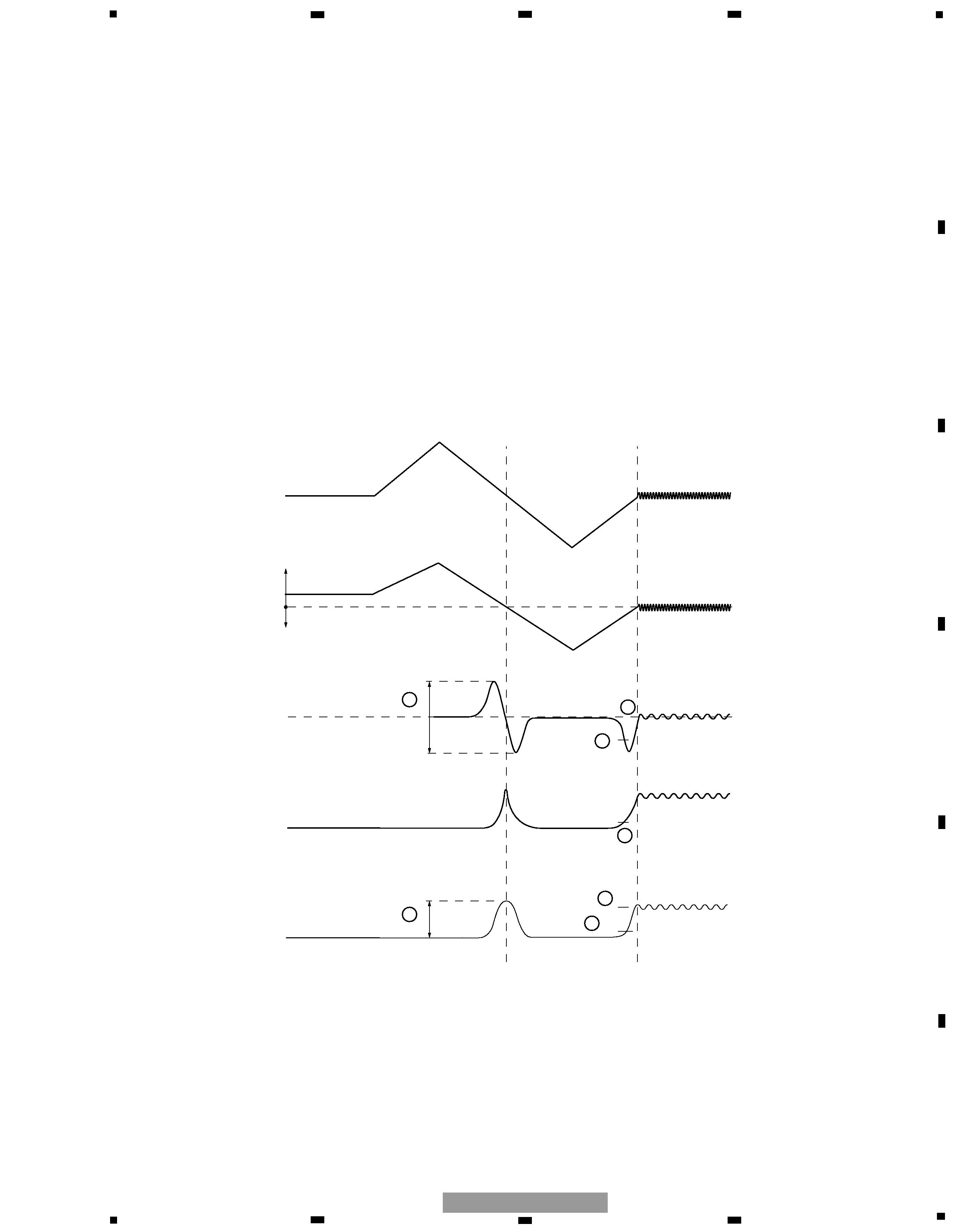
After a focus close command is issued, the following procedures are performed irrespective of DVDs and CDs:
1. Measuring and optimizing the signal levels
The pickup lens initially moves away from the disc, and then toward the disc. When the pickup lens passes the focal
point, the FE, AS and RFENV signal levels are measured to optimize the FE and AS signal levels (1 and 2 shown in
the above diagram).
Near the disk
Away from the disk
Lens
VHALF
Focal point
FE
RFENV
AS
3
6
7
4
5
1
2
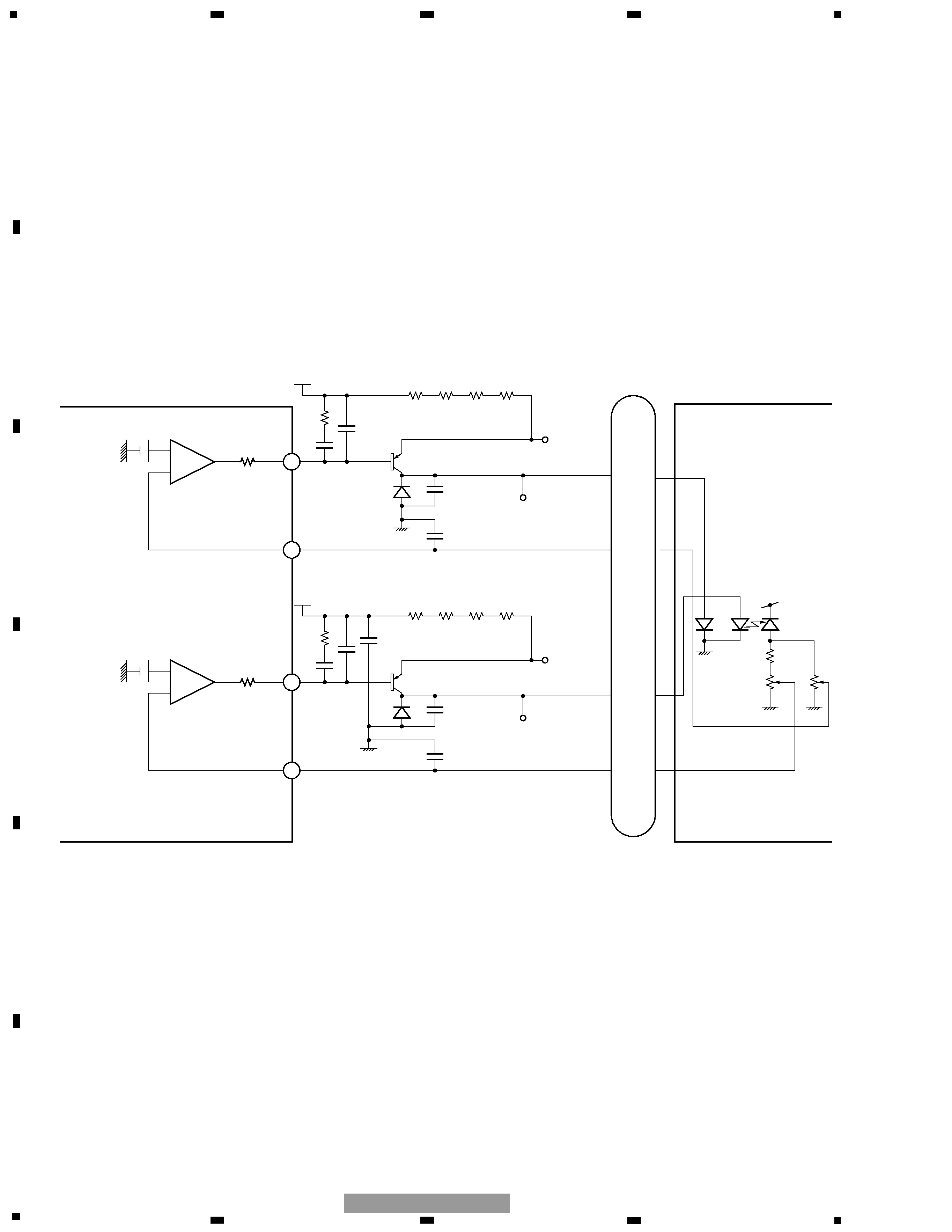
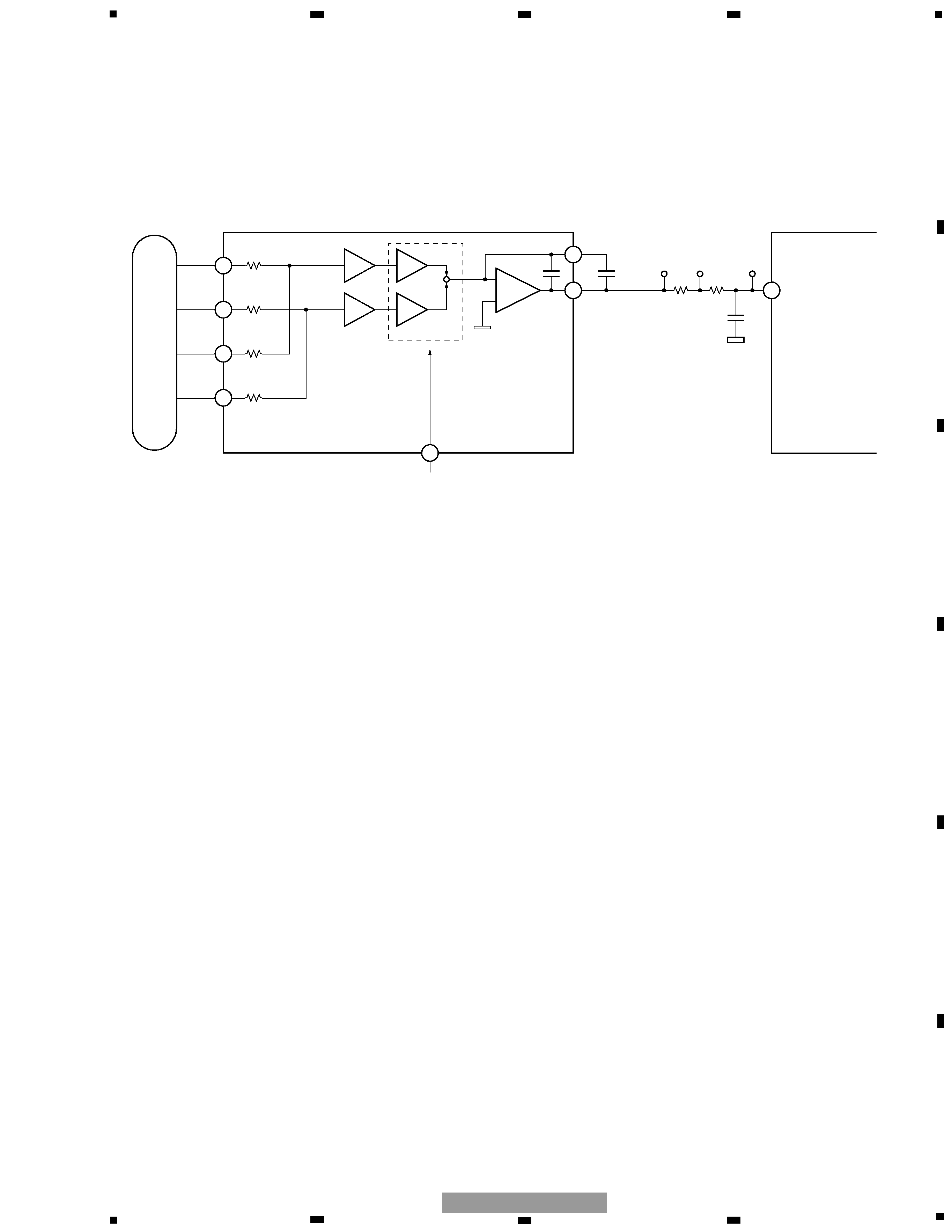
1.2 Optical disc controller (SODC) section (MNZS26EDCUB: IC1301)
The IC1301, an optical disc controller (SODC) for DVD-ROM/DVD players, is one of a signal processing LSI conforming
to the DVD standards.
This IC works as a servo controller for the focus, tracking and traverse operations, a spindle motor controller, a seek
controller, a digital signal processor for DVD-ROM/RAM reproduction (8/6 demodulation and error correction), and a
digital signal processor for CD-ROMs (error correction). In the DSC (Disc Servo Controller) employing an arithmetic
processor as a core, analog circuits such as A/D and D/A converters and PLL, and digital circuits including a PWM
converter and a cycle timer are contained. In the CIRC, a digital signal processor for CD-DA and CD-ROMs (EFM
demodulation and error correction), a spindle motor digital servo processor, and a 1-bit D/A converter with a digital
filter (with a secondary low-pass filter, differential OP amplifier output) are prepared. This LSI has easily realized a
complete CD/DVD-ROM system.
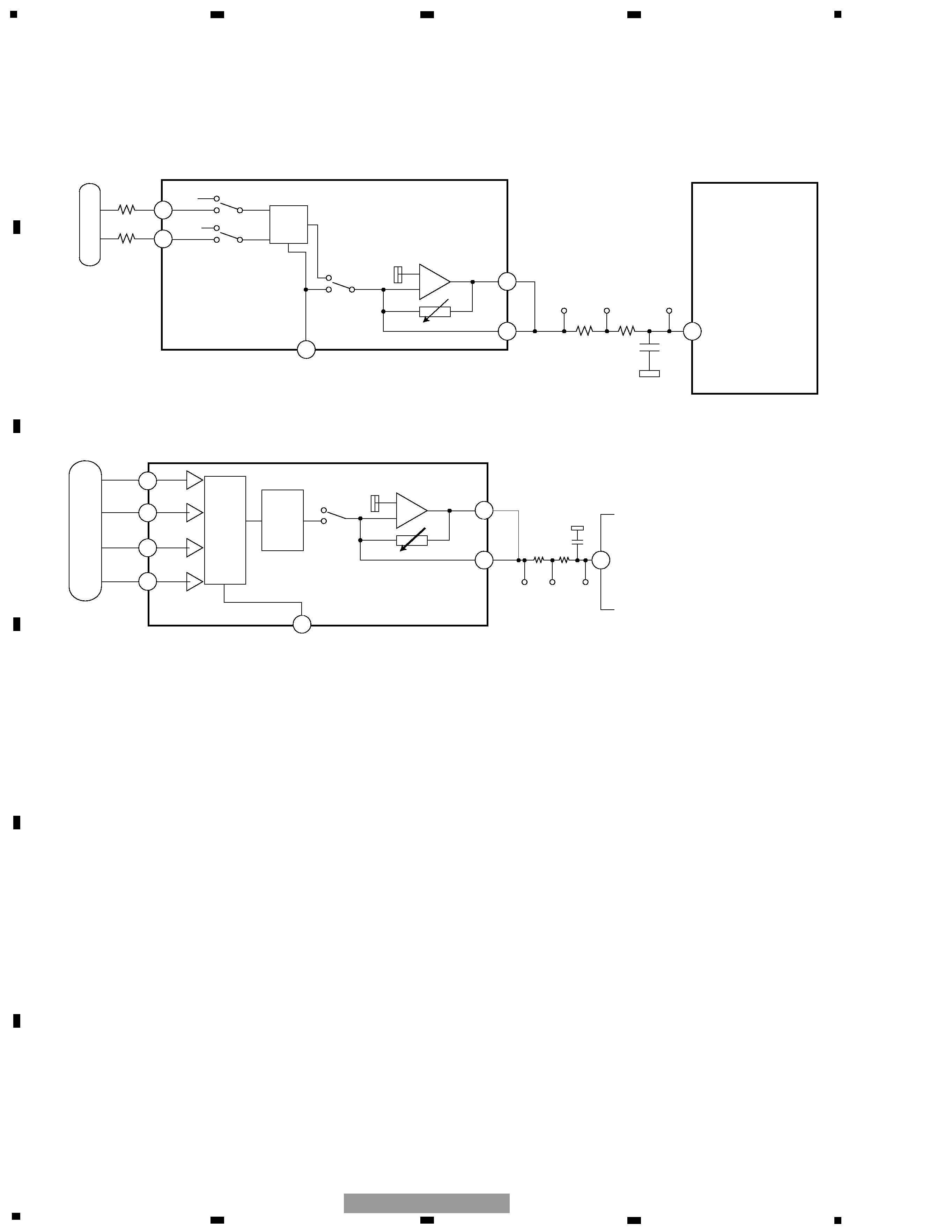
1.2.1 Focus close
FODRV

Reviews

There are no reviews of this manual yet.