PIONEER CP-7EX/SXTW/EW5 Owner's Manual

Cover page of PIONEER CP-7EX/SXTW/EW5 Owner's Manual

Owner's Manual for PIONEER CP-7EX/SXTW/EW5, downloadable as a PDF file.

Manual details

  • Immediate download after payment.
  • Delivered as a PDF file.
  • The manual has 40 pages
  • File size: 1.39 MB
  • Available language versions: Portuguese, Swedish, French, English, Russian, Spanish, Dutch, German, Danish, Italian, Finnish, Norwegian
  • Different language versions may vary sligthly in file size and page count.

We guarantee that...

  • our manuals are complete,
  • our manuals are checked with antivirus,
  • We'll issue refund if the manual is damaged, incomplete or unreadable (our refund policy)

Sample pages

Thumbnail of page 1Thumbnail of page 2Thumbnail of page 3Thumbnail of page 4
Thumbnail of page 5Thumbnail of page 6Thumbnail of page 7Thumbnail of page 8
Thumbnail of page 9
background image
CP-7EX
Speaker Stand / Socle d'enceinte / Lautsprecherständer /
Base per diffusori / Luidsprekerstandaard / Soportes de altavoz /
Suporte para colunas / Högtalarstativ / Højttalerstativ /
Høyttalerstativ / Kaiutinjalusta /
background image
CP-7EX
Speaker Stand / Socle d'enceinte / Lautsprecherständer /
Base per diffusori / Luidsprekerstandaard / Soportes de altavoz /
Suporte para colunas / Högtalarstativ / Højttalerstativ /
Høyttalerstativ / Kaiutinjalusta /
background image
2
En
Thank you for buying this Pioneer product. This speaker
stand should only be used with the S-7EX Pioneer speaker
system. Please read through these operating instructions for
proper assembly and use. After you have finished reading the
instructions, put them away in a safe place for future
reference.
Before you start
Before setting up your speaker system, we recommend
reading the operating instructions for your system thor-
oughly.
· Only use the screws supplied when fixing the speaker to
the speaker stand.
· Do not place the stand on an unstable and/or sloping
surface. The stand and speaker may fall and cause
injury.
· Do not use with any speaker system other than the one
for which the unit was designed. The stand may collapse
and be damaged and/or the speaker may fall and cause
injury.
· When moving the speaker and stand, first remove the
speaker from the stand, and then move the stand,
holding it by the two stems.
Installing the speaker stands
Place the stand on a stable, level surface; placing the stand
on an unstable surface can be dangerous.
Adjust the position as necessary to obtain optimal sound
from your system.
· Pioneer assumes no liability whatsoever for damages
resulting from assembly, improper mounting, insuffi-
cient reinforcement, misuse of the product, acts of
nature, etc.
Assembling the speaker stands
Assemble the speaker stands as illustrated below. Please
note that a flathead screwdriver will be necessary for
assembly. The following illustration shows the fully assem-
bled speaker stand:
Speaker support
Stand base
Stand stems
Screw slots
for securing
speaker
·
Align the screw slots on the stand base and screw
holes on the speaker support with the screw holes in
the two stems, then insert the screws and tighten.
The screw slots allow you to fine-tune the positioning of the
speaker.
55 mm
Black
(SBA6054)
40 mm
Black
Please note that sunken
screw holes are provided
in the speaker support.
(SBA6051)
Screws (Bind head, M6xL40)
Nut
Spike (SBA6053)
Spike base
(SLA1057)
Screws (Bind head, M6xL55)
Speaker
support
Stand
base
Stand
stems
· Make sure you assemble the stand on a flat surface that
is relatively soft (such as a carpet).
· Make sure the screws are inserted in the screw holes as
shown above (with the screw head hidden) when
securing the speaker. Improper setup could result in
damage or injury if the speaker falls from the stand.
background image
3
En
English
Using the spikes
The speaker stand includes spikes that you can use to isolate
the speaker from the floor. Spikes are recommended when
placing the stand on a thick carpet (for added stability), or for
better sound when placing the stand on a hard reverberant
surface (such as a concrete or wood floor). Use the supplied
spike bases to avoid scratching the floor or other surface
where the stand is placed.
1
2
Spike
Stand base plate
Nut
1
Attach the spikes to the nuts provided.
2
Attach all four spikes to the threaded metal inserts
at the base of the speaker stand.
3
Choose the location for speaker placement then put
the spike bases on the floor.
4
Place the stand so that the spikes are resting on the
spike bases on the floor.
Before placing the speaker on the speaker stand, make sure
the stand is stable and resting squarely on all four spikes.
· Note that these spikes are sharp metal and can cause
damage to flooring. Make sure to lay down a cloth or
suitable base before setting up.
· The spike bases should be placed as shown below (with
the depression on the top side).
· Make sure to use the spike bases provided to avoid
damaging the surface where you place the stand.
Attaching a speaker to the stand
To avoid accident or injury, please use screws to secure the
speaker to the speaker stand. Note that there are fastening
nuts provided on the speaker base (see below). Secure the
speaker to the speaker support using the washer, spring
washer and the 60 mm screws as shown below.
(SBA6058)
Speaker
base
Speaker
support
Washers (SBE6008)
Fastening nuts
Screws
(Bind head, M6xL60)
60 mm
Black
Spring washer
(SBE6007)
Screw slots
for securing
speaker
Cabinet and stand maintenance
· Use a polishing cloth or dry cloth to wipe off dust and
dirt.
· If the cabinet or stand is very dirty, use a soft cloth
dipped in some neutral cleanser diluted 5 or 6 times
with water. Finally, wipe again using a dry cloth. Do not
use furniture wax or cleaners.
· Never use thinners, benzine, insecticide sprays and
other chemicals on or near the cabinet or stand, since
these will corrode the surfaces.
background image
4
En
Published by Pioneer Corporation.
Copyright © 2005 Pioneer Corporation.
All rights reserved.
If you want to dispose this product, do not mix it with
general household waste. There is a separate collection
system for used electronic products in accordance with
legislation that requires proper treatment, recovery and
recycling.
Private households in the 25 member states of the EU, in
Switzerland and Norway may return their used electronic
products free of charge to designated collection facilities or to a
retailer (if you purchase a similar new one).
For countries not mentioned above, please contact your local
authorities for the correct method of disposal.
By doing so you will ensure that your disposed product under-
goes the necessary treatment, recovery and recycling and thus
prevent potential negative effects on the environment and
human health.
Part name
· Protector (Top)
· Protector (Middle)
· Protector (Bottom)
· Packing case
· Protection sheet
· Protection sheet
· Protection sheet
Replacement part numbers
Part no.
SHA6101
SHA6102
SHA6103
SHG6130
SHC6048
SHC6049
SHC6050
Specifications
External dimensions ............... 498 (W) x 310 (H) x 412 (D) mm
Weight .............................................................................. 14.0 kg
Supplied accessories
Stand base plate ........................................................................ 1
Speaker support ......................................................................... 1
Stems .......................................................................................... 2
Spikes (with attached nuts) [SBA6053] ................................... 4
Spike bases [SLA1057] .............................................................. 4
Screws (Bind head, M6xL55) [SBA6051] ................................. 6
Screws (Bind head, M6xL60) [SBA6058] ................................. 2
Screws (Bind head, M6xL40) [SBA6054] ................................. 6
Spring washers [SBE6007] ........................................................ 2
Washers [SBE6008] ................................................................... 2
These operating instructions [SRD6046] ................................. 1
· Specifications and design subject to possible modifica-
tion without notice, due to improvements.
· The product number are listed above in square brackets.
background image
5
Fr
FrançaisFrançais
Nous vous remercions pour l'achat de ce produit Pioneer. Ce
socle d'enceinte doit être utilisé uniquement avec l'enceinte
acoustique S-7EX de Pioneer. Veuillez lire attentivement ce
mode d'emploi pour assembler et utiliser correctement le
produit. Après avoir lu ces explications, rangez-les dans un
endroit sûr pour vous y référer éventuellement à l'avenir.
Avant de commencer
Avant d'installer les enceintes acoustiques, nous vous
conseillons de lire attentivement le mode d'emploi qui les
accompagne.
Attention
· Utilisez uniquement les vis fournies pour fixer l'enceinte
sur le socle d'enceinte.
· Ne placez pas le socle sur une surface instable et/ou
glissante, car le socle et l'enceinte pourraient tomber et
provoquer des blessures.
· N'utilisez avec aucune autre enceinte que celle pour
laquelle ce socle a été conçu. Le socle pourrait se
renverser et être endommagé et/ou l'enceinte pourrait
tomber et provoquer des blessures.
· Avant de déplacer l'enceinte et le socle, déposez d'abord
l'enceinte, puis déplacez le socle en le tenant par ses
deux montants.
Installation des socles d'enceinte
Placez le socle sur une surface stable et horizontale; il serait
dangereux de le poser sur une surface instable.
Ajustez la position selon les besoins de manière à obtenir de
votre enceinte un son optimal.
· Pioneer n'assume aucune responsabilité en cas de
dégâts, découlant d'une assemblage ou d'un montage
inadéquat, d'un renforcement insuffisant, d'une
utilisation inapproprié du produit, de catastrophes
naturelles, etc.
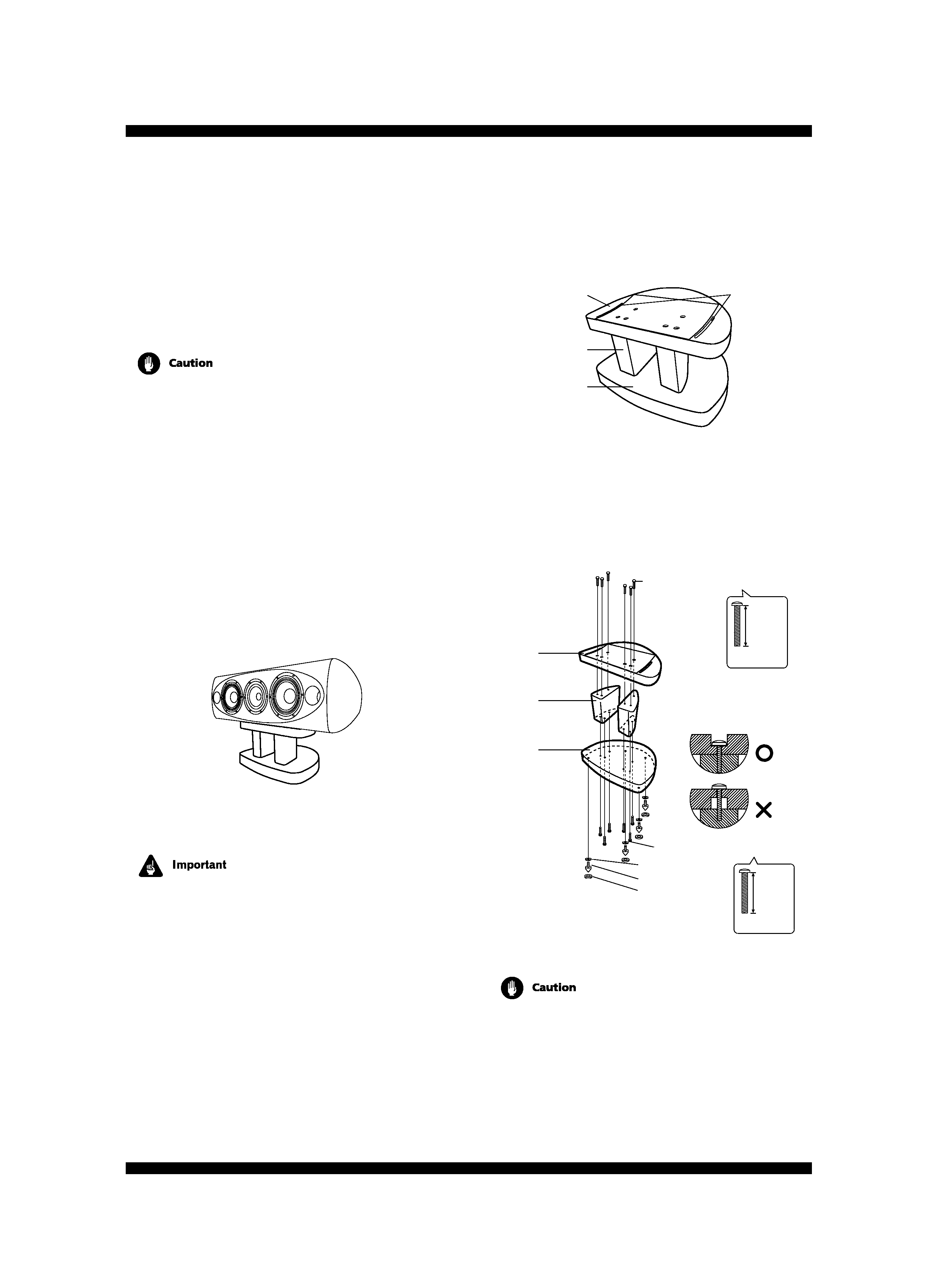
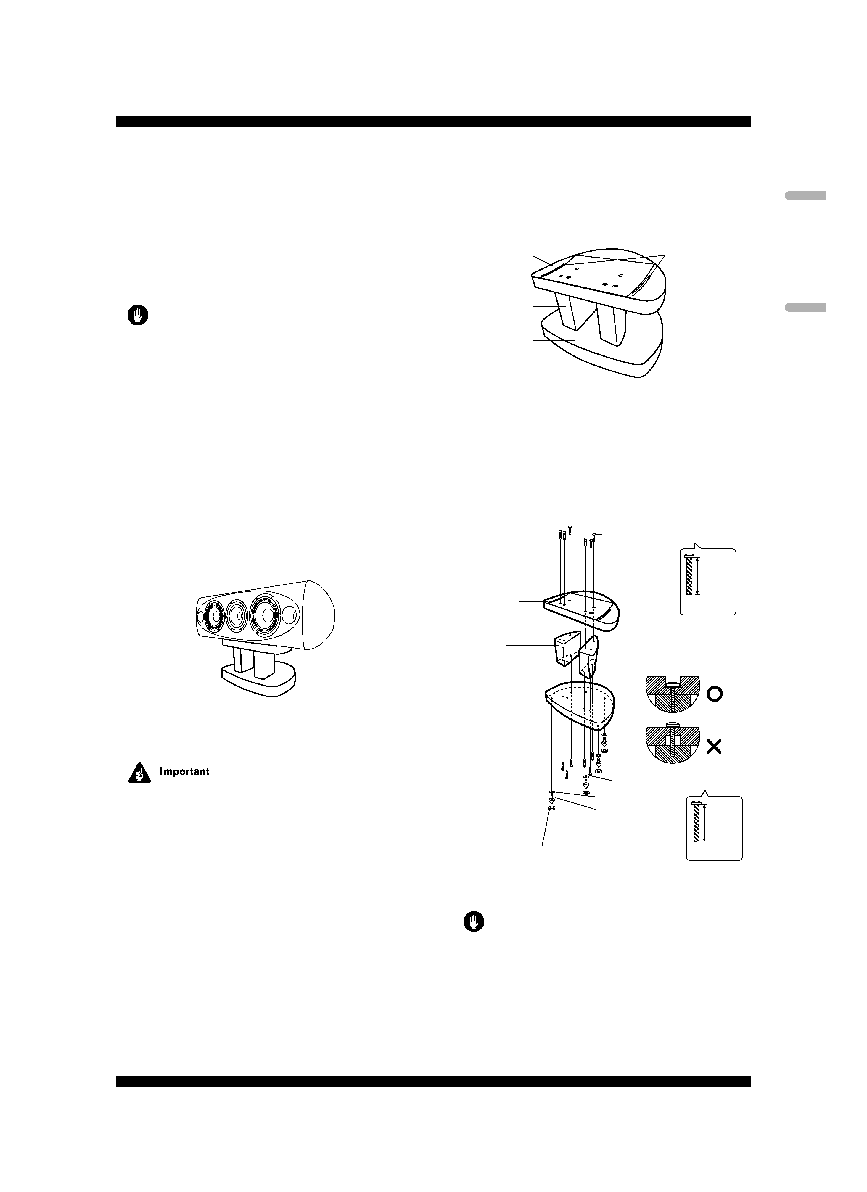
Assemblage des socles d'enceinte
Assemblez les socles d'enceinte comme illustré ci-dessous.
Notez qu'un tournevis à tête plate est requis pour cet assem-
blage. L'illustration suivante présente le socle d'enceinte à
l'état assemblé.
Rainures de vis
pour fixation
de l'enceinte
Support
d'enceinte
Base du socle
Montants
du socle
·
Faites correspondre les rainures de vis sur la base du
socle et les orifices de vis sur le support d'enceinte avec
les orifices de vis dans les deux montants, puis insérez les
vis et serrez-les.
Les rainures de vis permettent d'ajuster avec précision le
positionnement de l'enceinte.
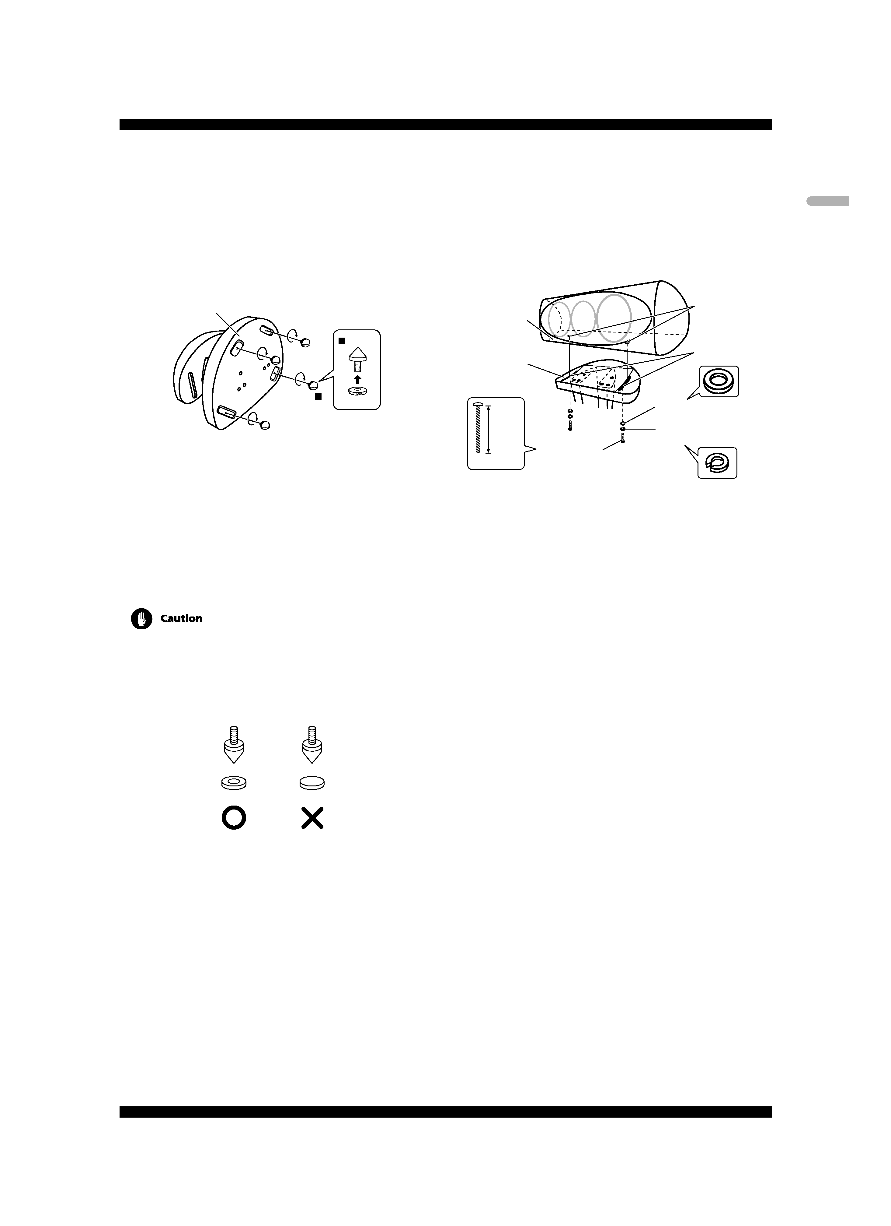
55 mm
Noir
(SBA6054)
40 mm
Noir
Notez que des orifices
pour vis noyée sont prévu
sur le support
(SBA6051)
Vis (tête intégrée, M6xL40)
Écrou
Pointe de
découplage
(SBA6053)
Vis (tête intégrée, M6xL55)
Support
d'enceinte
Base du
socle
Montants
du socle
Base pour pointe de
découplage (SLA1057)
Attention
· Prenez soin d'assembler le socle sur une surface plate
qui soit relativement souple (comme un tapis).
· Lors de la fixation de l'enceinte, prenez soin que les vis
soient insérées dans les orifices de vis comme illustré ci-
dessus (leur tête étant noyée). Une installation
inadéquate pourrait provoquer des dégâts ou des
blessures si l'enceinte devait tomber de son socle.
English

Reviews

There are no reviews of this manual yet.