PIONEER CDXPD6 Service Manual

Cover page of PIONEER CDXPD6 Service Manual

Service Manual for PIONEER CDXPD6, downloadable as a PDF file.

Manual details

  • Immediate download after payment.
  • Delivered as a PDF file.
  • The manual has 90 pages
  • File size: 6.17 MB
  • Available language versions: English
  • Different language versions may vary sligthly in file size and page count.

We guarantee that...

  • our manuals are complete,
  • the manual includes circuit diagrams,
  • our manuals are checked with antivirus,
  • We'll issue refund if the manual is damaged, incomplete or unreadable (our refund policy)

Sample pages

Thumbnail of page 1Thumbnail of page 2Thumbnail of page 3Thumbnail of page 4
Thumbnail of page 5Thumbnail of page 6Thumbnail of page 7Thumbnail of page 8
Thumbnail of page 9
background image
PIONEER ELECTRONIC CORPORATION
4-1, Meguro 1-Chome, Meguro-ku, Tokyo 153-8654, Japan
PIONEER ELECTRONICS SERVICE INC.
P.O.Box 1760, Long Beach, CA 90801-1760 U.S.A.
PIONEER ELECTRONIC [EUROPE] N.V.
Haven 1087 Keetberglaan 1, 9120 Melsele, Belgium
PIONEER ELECTRONICS ASIACENTRE PTE.LTD. 253 Alexandra Road, #04-01, Singapore 159936
C PIONEER ELECTRONIC CORPORATION 1999
K-ZZD. FEB. 1999 Printed in Japan
ORDER NO.
CRT2372
6
5
4
2
1
3
MULTI-COMPACT DISC PLAYER
CDX-PD6
UC
Service
Manual
CONTENTS
1. SAFETY INFORMATION ............................................2
2. EXPLODED VIEWS AND PARTS LIST .......................3
3. BLOCK DIAGRAM AND SCHEMATIC DIAGRAM ...10
4. PCB CONNECTION DIAGRAM ................................26
5. ELECTRICAL PARTS LIST ........................................42
6. ADJUSTMENT..........................................................46
7. GENERAL INFORMATION .......................................48
7.1 DIAGNOSIS ........................................................48
7.1.1 TEST MODE ..............................................48
7.1.2 DISASSEMBLY .........................................55
7.2 IC ........................................................................58
8. OPERATIONS AND SPECIFICATIONS.....................63
- See the separate manual CX-890(CRT2376) for the CD mechanism description, disassembly and circuit
description.
- The CD mechanism employed in this model is one of G1 series.
background image
2
CDX-PD6
- CD Player Service Precautions
1. For pickup unit(CXX1311) handling, please refer
to"Disassembly"(see page 55).
During replacement, handling precautions shall be
taken to prevent an electrostatic discharge(protection
by a short pin).
2. During disassembly, be sure to turn the power off
since an internal IC might be destroyed when a con-
nector is plugged or unplugged.
3. Please checking the grating after changing the ser-
vice pickup unit(see page 46).
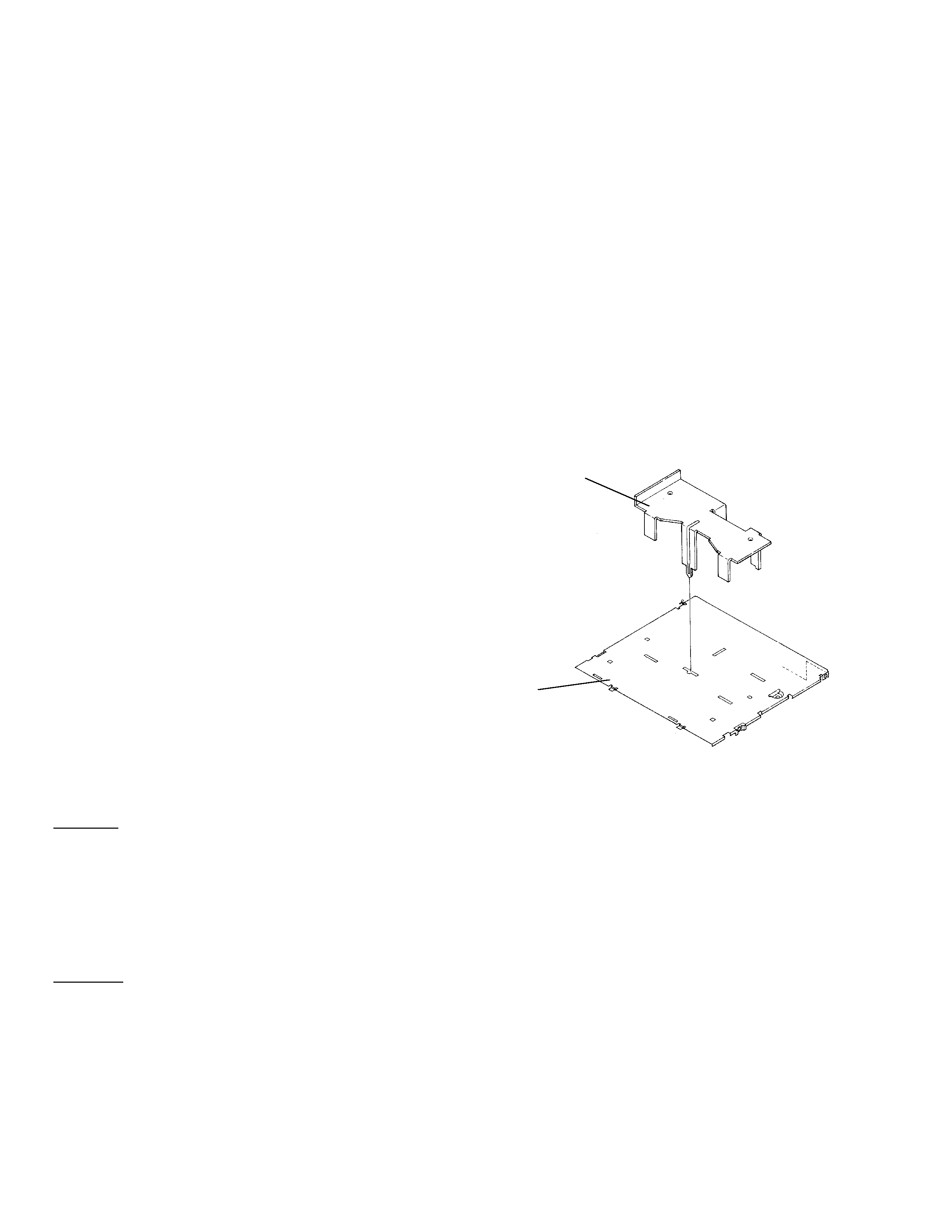
- When the Repair is Complete
When the repair is complete, make the CD mechanism
ready for transportation
implementing the following procedures:
1. Press the changer side 1 and 4 simultaneously to turn
the ACC on.
2. As the ACC is turned on, the disc indicator blinks in
red.
3. When the blinking is stopped, the mechanism is
ready for the transportation.
4. Attach the Transportation Bracket (CNC7878). Now
you can transport it.(See the figure below) (The
Bracket used on the CDX-PD6/UC is recommended
for the transportation purpose.)
CAUTION
This service manual is intended for qualified service technicians; it is not meant for the casual do-it-yourselfer.
Qualified technicians have the necessary test equipment and tools, and have been trained to properly and safely repair
complex products such as those covered by this manual.
Improperly performed repairs can adversely affect the safety and reliability of the product and may void the warranty.
If you are not qualified to perform the repair of this product properly and safely; you should not risk trying to do so
and refer the repair to a qualified service technician.
WARNING
This product contains lead in solder and certain electrical parts contain chemicals which are known to the state of
California to cause cancer, birth defects or other reproductive harm.
Health & Safety Code Section 25249.6 - Proposition 65
1. SAFETY INFORMATION
Transportation Basket
(CNC7878)
Case
(CNB2354)
background image
3
CDX-PD6
1 Polyethylene Bag
CEG1116
2-1 Owner's Manual
CRD3000
(English, French)
2-2 Installation Manual
CRD3001
(English, French)
*
2-3 Warranty Card
CRY1070
3 Screw Assy
CEA2046
*
4 Polyethylene Bag
CEG-127
5 Screw
BMZ50P080FMC
6 Carton
CHG3787
7 Contain Box
CHL3787
8 Protector
CHP2123
9 Cover
CEG1177
10 Protector
CHP2124
Mark No. Description
Part No.
Mark No. Description
Part No.
- PACKING SECTION PARTS LIST
NOTE:
- Parts marked by "*" are generally unavailable because they are not in our Master Spare Parts List.
- Screws adjacent to
mark on the product are used for disassembly.
2. EXPLODED VIEWS AND PARTS LIST
2.1 PACKING
background image
4
CDX-PD6
2.2 EXTERIOR
background image
CDX-PD6
1 Screw
BMZ20P020FMC
2 Screw
BMZ26P030FMC
3 Screw
BMZ26P060FMC
4 Chassis
CNA2178
5 Case
CNB2354
6 Side Frame
CNB2484
7 Bracket
CNC7878
8 Bracket
CNC8026
9 Front Frame
CNC8027
10 Holder
CNC8028
11 Insulator
CNM5969
12 Insulator
CNM5970
13 PCB
CNP5516
*
14 Caution Label
CRP1200
15 Holder
CNV5543
16 Extended Unit
CWM6526
17 Cord
CDE6020
18 Cord
CDE6019
19 Connector(CN102)
CKS2200
20 Connector(CN103)
CKS3597
21 Connector(CN701)
CKS3970
22 Connector(CN101)
CKS3989
23 Holder
CNC8031
24 Screw
BPZ20P060FMC
25 Button(EJECT)
CAC5821
26 Button(1-6)
CAC6115
27 Door
CAT2067
28 Washer
CBF1038
29 Spring
CBH2200
30 Spring
CBH2201
31 Connector
CDE5858
32 PCB
CNP5281
33 Gear
CNV5547
34 Arm
CNV5548
35 Guide
CNV5818
36 Keyboard Unit
CWM6131
37 Connector(CN902)
CKS3992
38 Connector(CN903)
CKS3992
39 Connector(CN901)
CKS4053
40 Bracket Unit
CXB3111
41 Grille Unit
CXB4000
42 Screw
IMS20P040FMC
43 CD Mechanism Module
CXK4701
44 Screw
IMS20P040FMC
45 Screw
IMS26P040FMC
*
46 Lighting Conductor
CNV5546
*
47 Lighting Conductor
CNV5545
48 Transistor(Q708)
2SB1335A
49 Damper
CNV5120
50 Holder
CNC7826
51 Screw(M2x2)
CBA1250
52 Sheet
CNM5981
53 Holder
CNC7477
54 Spring(Front)
CBH2066
55 Spring(Right Rear)(Black) CBH2067
56 Spring(Left Rear)
CBH2065
57 Cap
CNS1472
58 Resistor
RS1/2PMF102J
59 Sheet
CNM6318
- EXTERIOR SECTION PARTS LIST
Mark No. Description
Part No.
Mark No. Description
Part No.
5

Reviews

There are no reviews of this manual yet.