PIONEER ELECTRONIC CORPORATION
4-1, Meguro 1-Chome, Meguro-ku, Tokyo 153-8654, Japan
PIONEER ELECTRONICS SERVICE INC.
P.O.Box 1760, Long Beach, CA 90801-1760 U.S.A.
PIONEER ELECTRONIC [EUROPE] N.V.
Haven 1087 Keetberglaan 1, 9120 Melsele, Belgium
PIONEER ELECTRONICS ASIACENTRE PTE.LTD. 253 Alexandra Road, #04-01, Singapore 159936
C PIONEER ELECTRONIC CORPORATION 1999
K-ZZY. MAY 1999 Printed in Japan
ORDER NO.
CRT2388
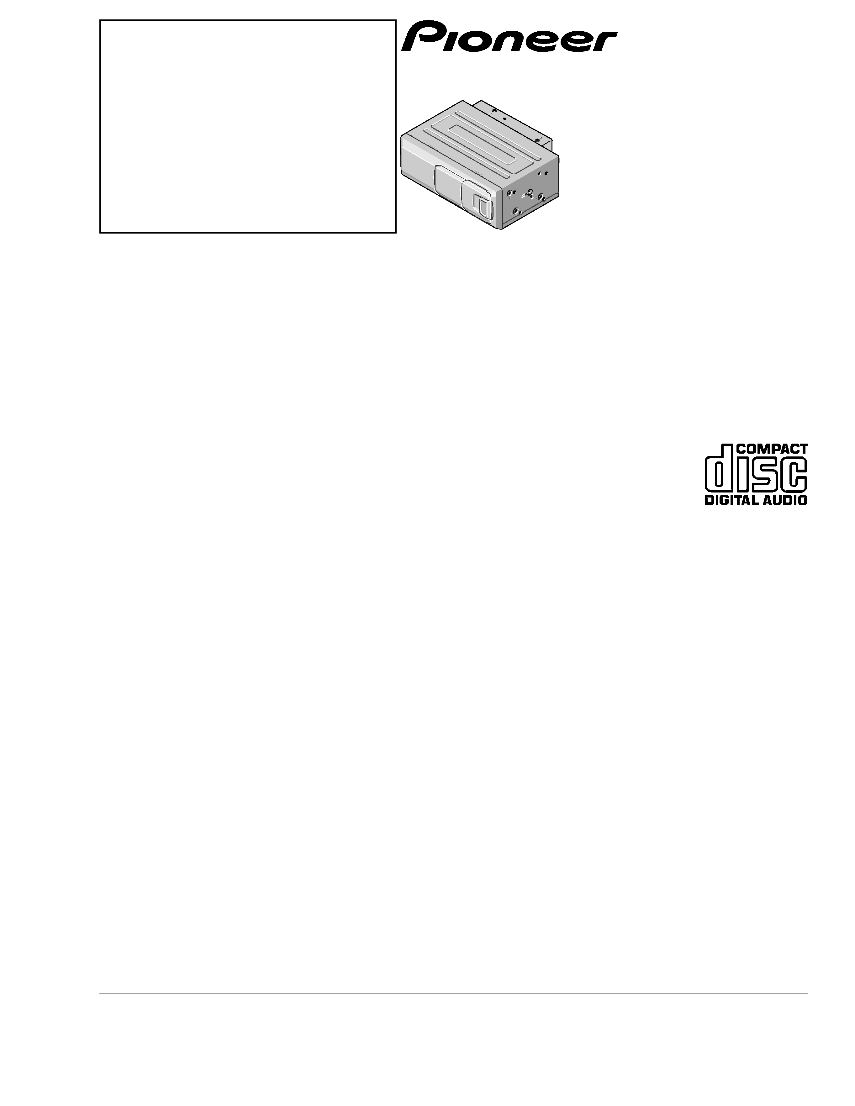
VOICE CONTROL MULTI-CD PLAYER
CDX-P2050VC
X1N/UC
Service
Manual
CONTENTS
1. SAFETY INFORMATION ............................................3
2. EXPLODED VIEWS AND PARTS LIST .......................4
3. BLOCK DIAGRAM AND SCHEMATIC DIAGRAM ...12
4. PCB CONNECTION DIAGRAM ................................26
5. ELECTRICAL PARTS LIST ........................................34
6. ADJUSTMENT..........................................................39
7. GENERAL INFORMATION .......................................45
7.1 DIAGNOSIS ........................................................45
7.1.1 TEST MODE ..............................................45
7.1.2 DISASSEMBLY .........................................54
7.2 IC .........................................................................56
8. OPERATIONS AND SPECIFICATIONS.....................65
- See the separate manual CX-938(CRT2357) for the CD mechanism description, disassembly and circuit
description.
- The CD mechanism employed in this model is one of C8 series.
CDX-P2050VC/X1N/UC
CDX-P2050VN X1N/EW
CDX-P2050VS X1N/EW