PIONEER CORPORATION
4-1, Meguro 1-Chome, Meguro-ku, Tokyo 153-8654, Japan
PIONEER ELECTRONICS SERVICE INC.
P.O.Box 1760, Long Beach, CA 90801-1760 U.S.A.
PIONEER EUROPE NV
Haven 1087 Keetberglaan 1, 9120 Melsele, Belgium
PIONEER ELECTRONICS ASIACENTRE PTE.LTD. 253 Alexandra Road, #04-01, Singapore 159936
C PIONEER CORPORATION 2000
K-ZZY. DEC. 2000 Printed in Japan
ORDER NO.
CRT2591
MULTI-COMPACT DISC PLAYER
CDX-P1270
X1N/UC
Service
Manual
CDX-P1270/X1N/UC
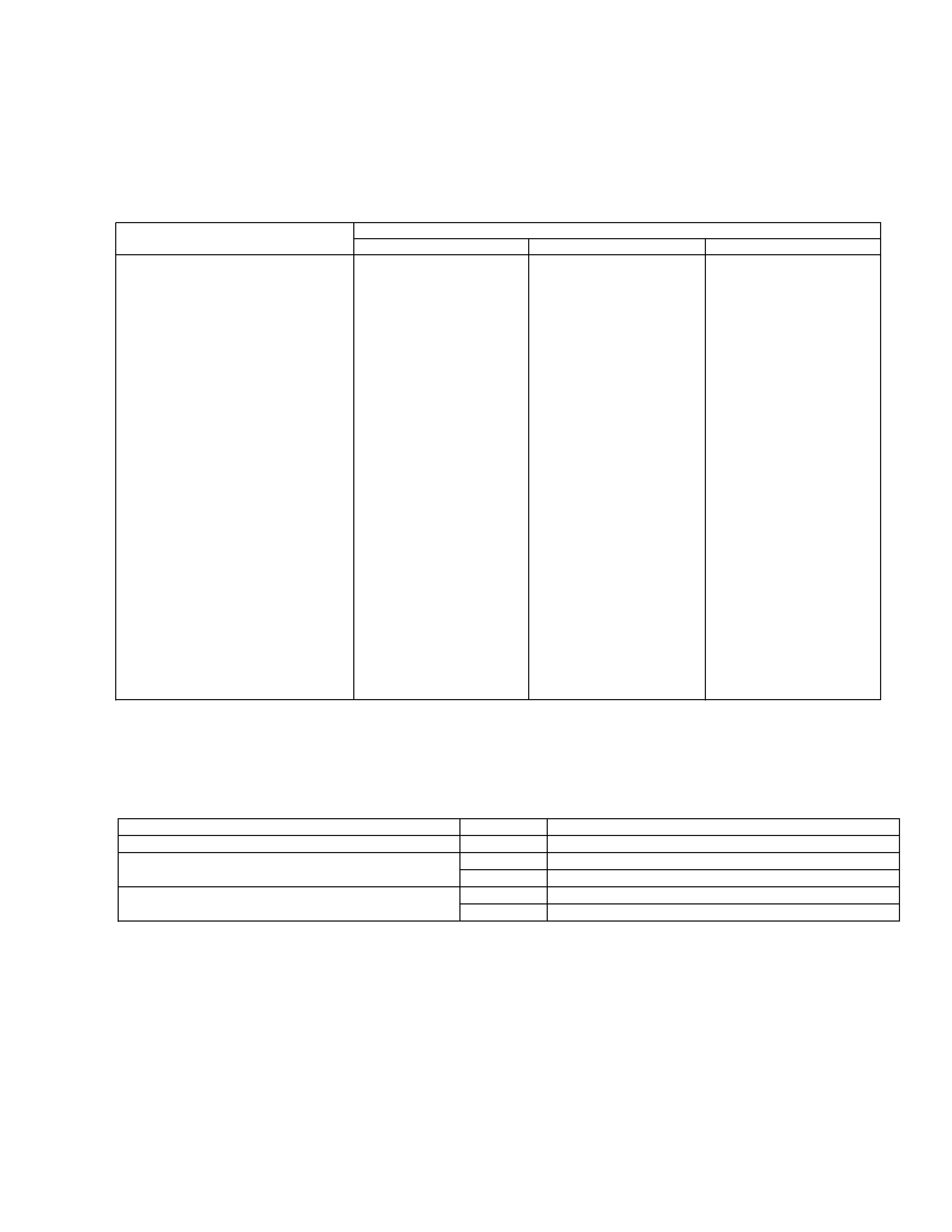
- This service manual should be used together with the following manual(s):
Model No.
Order No.
Mech. Module
Remarks
CX-938
CRT2357
C8
CD Mech. Module:Circuit Description, Mech. Description, Disassembly
CONTENTS
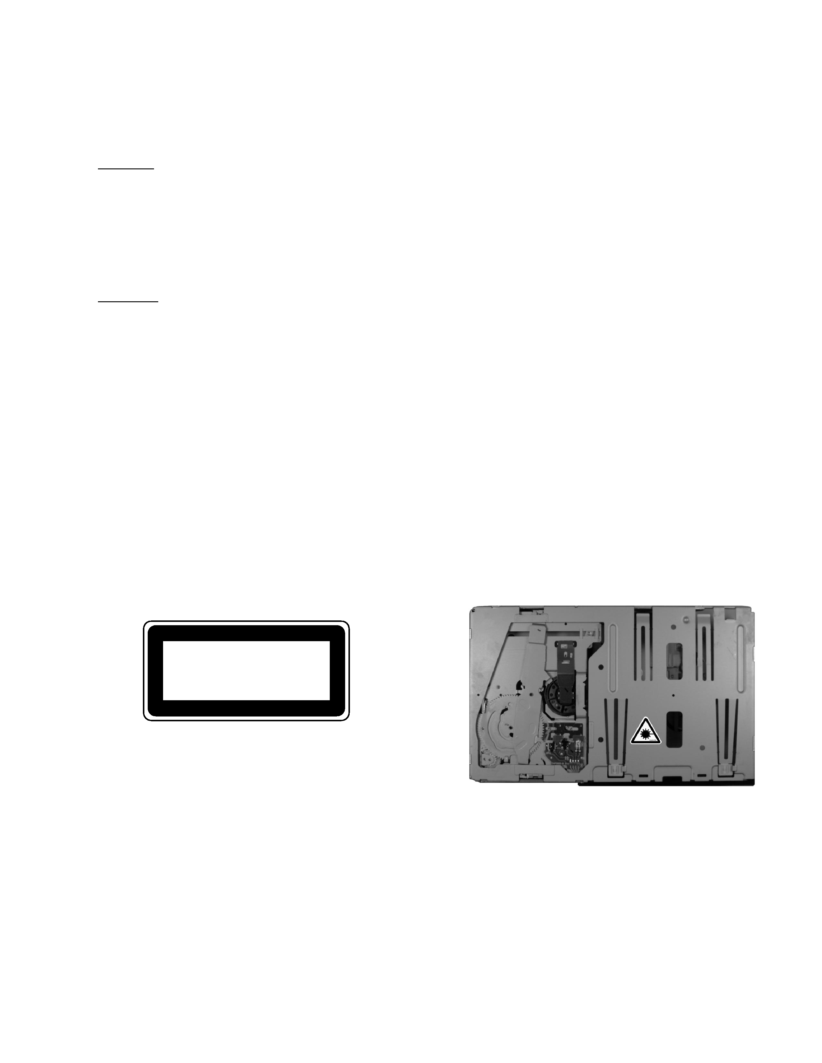
1. SAFETY INFORMATION ............................................3
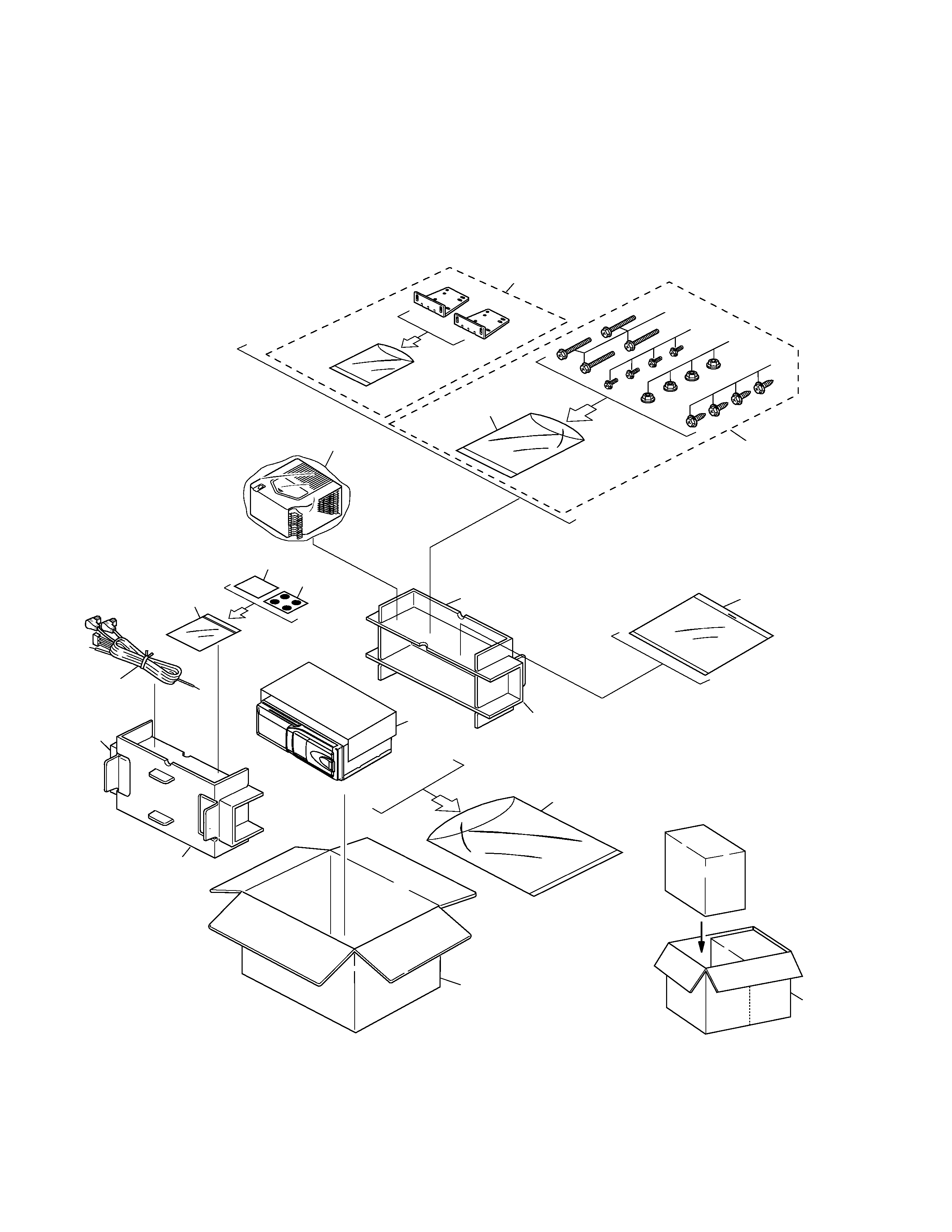
2. EXPLODED VIEWS AND PARTS LIST .......................4
3. BLOCK DIAGRAM AND SCHEMATIC DIAGRAM ...12
4. PCB CONNECTION DIAGRAM ................................22
5. ELECTRICAL PARTS LIST ........................................28
6. ADJUSTMENT..........................................................31
7. GENERAL INFORMATION .......................................40
7.1 DIAGNOSIS ........................................................40
7.1.1 TEST MODE ..............................................40
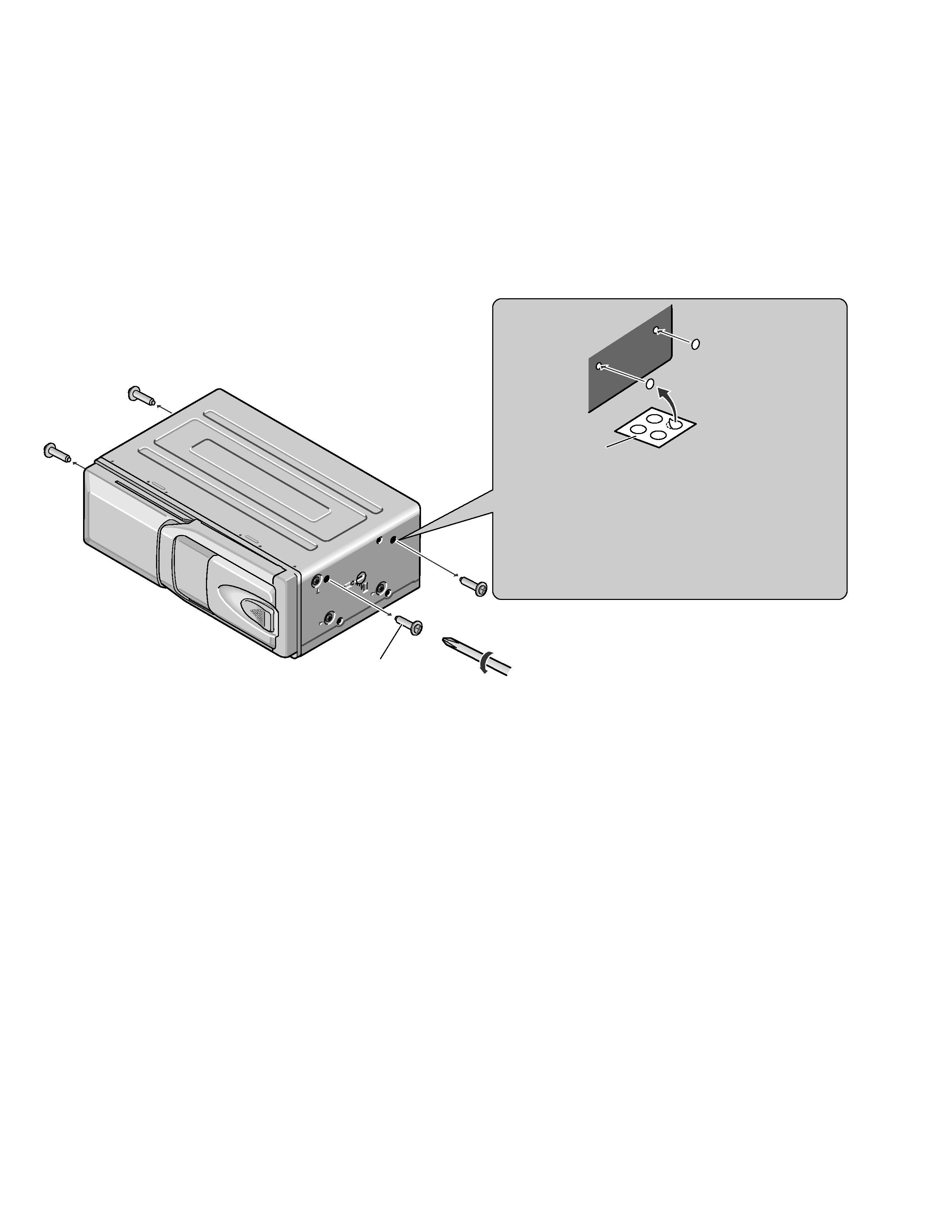
7.1.2 DISASSEMBLY .........................................44
7.1.3 CONNECTOR FUNCTION DESCRIPTION46
7.2 IC .........................................................................47
7.3 OPERATIONAL FLOW CHART ...........................49
8. OPERATIONS AND SPECIFICATIONS.....................50
CDX-P1270 X1N/EW
CDX-P1270 X1N/ES