PIONEER CDXMG2006ZRN Service Manual

Cover page of PIONEER CDXMG2006ZRN Service Manual

Service Manual for PIONEER CDXMG2006ZRN, downloadable as a PDF file.

Manual details

  • Immediate download after payment.
  • Delivered as a PDF file.
  • The manual has 88 pages
  • File size: 5.81 MB
  • Available language versions: English
  • Different language versions may vary sligthly in file size and page count.

We guarantee that...

  • our manuals are complete,
  • the manual includes circuit diagrams,
  • our manuals are checked with antivirus,
  • We'll issue refund if the manual is damaged, incomplete or unreadable (our refund policy)

Sample pages

Thumbnail of page 1Thumbnail of page 2Thumbnail of page 3Thumbnail of page 4
Thumbnail of page 5Thumbnail of page 6Thumbnail of page 7Thumbnail of page 8
Thumbnail of page 9
background image
PIONEER CORPORATION
4-1, Meguro 1-Chome, Meguro-ku, Tokyo 153-8654, Japan
PIONEER ELECTRONICS SERVICE INC.
P.O.Box 1760, Long Beach, CA 90801-1760 U.S.A.
PIONEER EUROPE N.V.
Haven 1087 Keetberglaan 1, 9120 Melsele, Belgium
PIONEER ELECTRONICS ASIACENTRE PTE.LTD. 253 Alexandra Road, #04-01, Singapore 159936
C PIONEER CORPORATION 2000
K-ZZB. FEB. 2000 Printed in Japan
ORDER NO.
CRT2412
6 DISC IN-DASH CD CHANGER
CDX-MG2006ZRN
EW
Service
Manual
RENAULT
CONTENTS
1. SAFETY INFORMATION ............................................2
2. EXPLODED VIEWS AND PARTS LIST .......................3
3. BLOCK DIAGRAM AND SCHEMATIC DIAGRAM ...10
4. PCB CONNECTION DIAGRAM ................................26
5. ELECTRICAL PARTS LIST ........................................42
6. ADJUSTMENT..........................................................46
7. GENERAL INFORMATION .......................................48
7.1 DIAGNOSIS ........................................................48
7.1.1 TEST MODE ..............................................48
7.1.2 DISASSEMBLY .........................................54
7.1.3 CONNECTOR FUNCTION DESCRIPTION .......58
7.2 IC ........................................................................59
7.3 SYSTEM BLOCK DIAGRAM ..............................61
8. OPERATIONS AND SPECIFICATIONS.....................62
VEHICLE
DESTINATION
PRODUCED AFTER
RENAULT PART No.
ID No.
PIONEER MODEL No.
ESPACE, AVANTIME
EUROPE
April 2000
6025 40 2760
CDX-MG2006ZRN/EW
- This service manual should be used together with the following manual(s):
Model No.
Order No.
Mech. Module
Remarks
CX-890
CRT2376
G1
CD Mechanism Module:Circuit Description, Mechanism Description, Disassembly
background image
2
CDX-MG2006ZRN
- CD Player Service Precautions
1. For pickup unit(CXX1311) handling, please refer
to"Disassembly"(see page 54).
During replacement, handling precautions shall be
taken to prevent an electrostatic discharge(protection
by a short pin).
2. During disassembly, be sure to turn the power off
since an internal IC might be destroyed when a con-
nector is plugged or unplugged.
3. Please checking the grating after changing the ser-
vice pickup unit(see page 46).
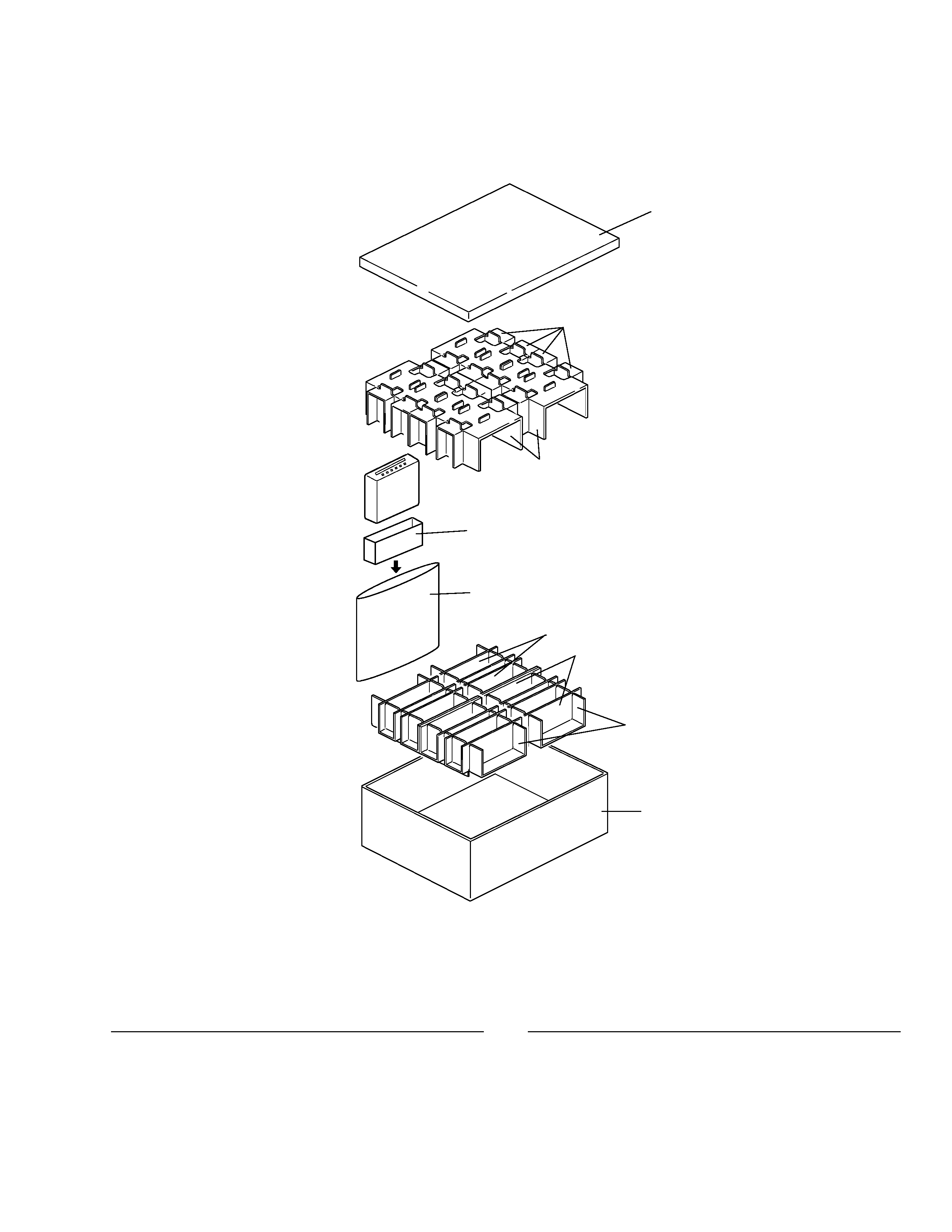
- When the Repair is Complete
When the repair is complete, make the CD mechanism
ready for transportation implementing the following
procedures:
1. Press the changer side 1 and 4 simultaneously to turn
the ACC on.
2. As the ACC is turned on, the disc indicator blinks in
red.
3. When the blinking is stopped, the mechanism is
ready for the transportation.
4. Attach the Transportation Bracket (CNC7878). Now
you can transport it.(See the figure below)
Transportation Bracket
(CNC7878)
Case
(CNB2527)
1. SAFETY INFORMATION
This service manual is intended for qualified service technicians; it is not meant for the casual do-it-yourselfer.
Qualified technicians have the necessary test equipment and tools, and have been trained to properly and safely repair
complex products such as those covered by this manual.
Improperly performed repairs can adversely affect the safety and reliability of the product and may void the warranty.
If you are not qualified to perform the repair of this product properly and safely; you should not risk trying to do so
and refer the repair to a qualified service technician.
1. Safety Precautions for those who Service this Unit.
· When checking or adjusting the emitting power of the laser diode exercise caution in order to get safe, reliable
results.
Caution:
1. During repair or tests, minimum distance of 13cm from the focus lens must be kept.
2. During repair or tests, do not view laser beam for 10 seconds or longer.
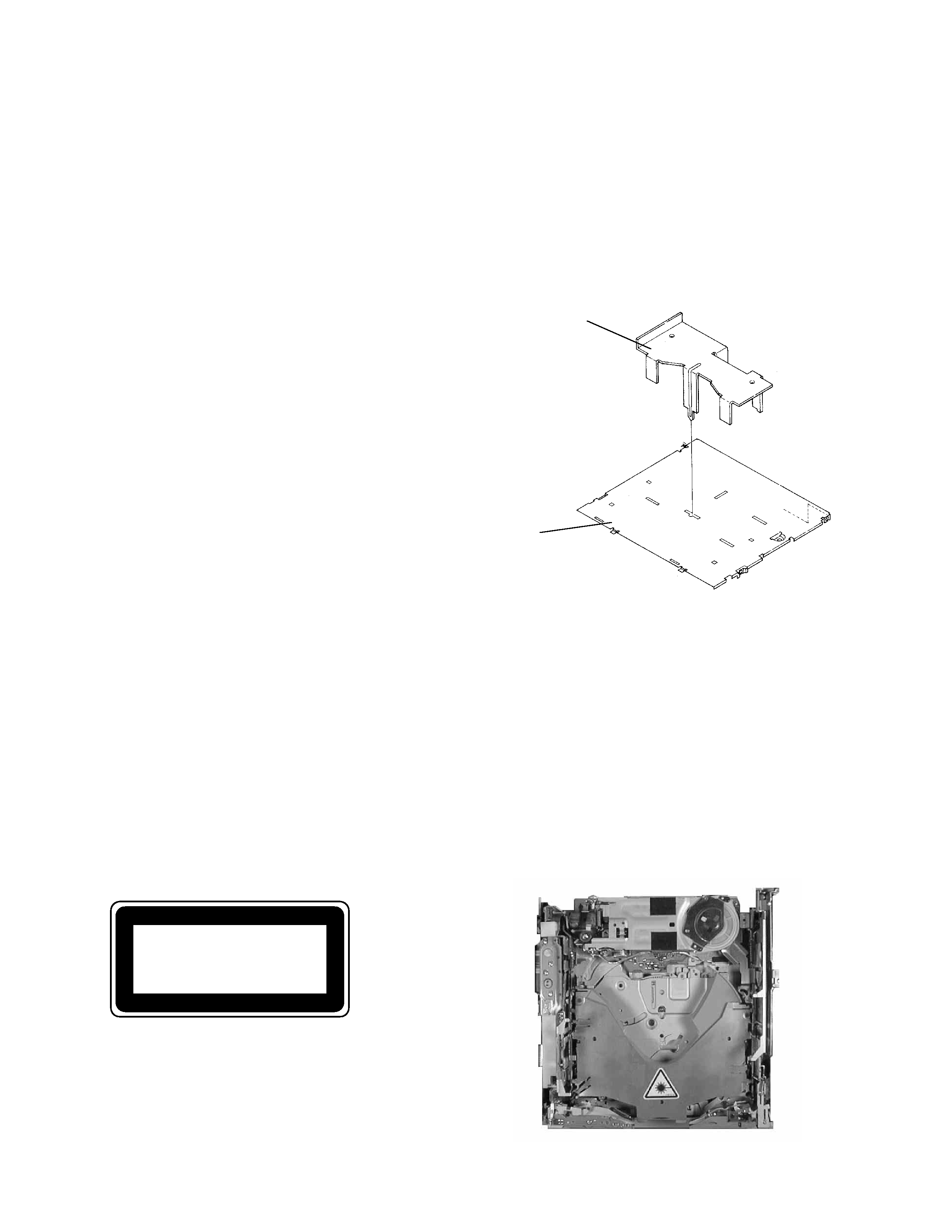
2. A "CLASS 1 LASER PRODUCT" label is affixed to the
bottom of the player.
3. The triangular label is attached to the mechanism
unit holder.
CLASS 1
LASER PRODUCT
4. Specifications of Laser Diode
Specifications of laser radiation fields to which human access is possible during service.
Wavelength
=
800 nanometers
background image
CDX-MG2006ZRN
1 Lid
CHW1584
*
2 Protector
CHP2235
*
3 Protector
CHP2234
*
4 Protector
CHP2237
*
5 Protector
CHP2236
*
6 Protector
CHP2238
7 Polyethylene Bag
CEG1042
*
8 Contain Box
CHL3990
Mark No. Description
Part No.
Mark No. Description
Part No.
- PACKING SECTION PARTS LIST
NOTE:
- Parts marked by "*" are generally unavailable because they are not in our Master Spare Parts List.
- Screws adjacent to
mark on the product are used for disassembly.
2. EXPLODED VIEWS AND PARTS LIST
2.1 PACKING
3
1
2
3
6
7
5
8
4
4
background image
4
CDX-MG2006ZRN
2.2 EXTERIOR
background image
CDX-MG2006ZRN
1 Screw
BMZ20P020FMC
2 Screw
BMZ26P030FMC
3 Screw
BMZ26P060FMC
4 Connector
CDE6144
5 Screw
IMS26P040FMC
6 Case
CNB2527
7 Side Frame
CNB2528
8 Case
CNB2529
9 Bracket
CNC7878
10 Front frame
CNC8574
11 Bracket
CNC8816
12 Insulator
CNM5969
13 Insulator
CNM6248
14 Insulator
CNM6532
15 Insulator
CNM6533
16 PCB
CNP5516
17 Clamper
CNV5150
18 Bush
CNV3253
19 Holder
CNV5543
20 Connector Unit
CWM6823
21 Plug(CN705)
CKS2372
22 Connector(CN704)
CKS3180
23 Connector(CN703)
CKS4120
24 Holder
CNC8575
25 Extension Unit
CWM6824
26 Connector(CN777)
CKS3747
27 Connector(CN701)
CKS3747
28 Connector(CN101)
CKS3989
29 Holder
CNC8031
30 Chassis Unit
CXB4792
31 Screw
BPZ20P080FMC
32 Button(1-6)
CAC6344
33 Button(EJECT)
CAC6345
34 Door
CAT2185
35 Washer
CBF1038
36 Spring
CBH2200
37 Spring
CBH2201
38 Connector
CDE6143
39 Insulator
CNM5331
40 Insulator
CNM6818
41 Grille
CNS6101
42 Gear
CNV5547
43 Arm
CNV5548
44 Lighting Conductor
CNV6028
45 Lighting Conductor
CNV6029
46 Holder
CNV6030
47 Keyboard Unit
CWM6822
48 Connector(CN901)
CKS3748
49 Bracket Unit
CXB3111
50 Screw
IMS20P040FMC
51 CD Mechanism Module(G1) CXK4700
52 Screw
IMS20P040FMC
53 Damper
CNV5120
54 Holder
CNC7826
55 Screw(M2x2)
CBA1250
56 Holder
CNC7477
57 Sheet
CNM5981
58 Sheet
CNM6318
59 Spring(Front)
CBH2409
60 Spring(Right Rear)(Black) CBH2361
61 Spring(Left Rear)
CBH2365
62 Transistor(Q708)
2SB1335A
- EXTERIOR SECTION PARTS LIST
Mark No. Description
Part No.
Mark No. Description
Part No.
5

Reviews

There are no reviews of this manual yet.