PIONEER CORPORATION
4-1, Meguro 1-Chome, Meguro-ku, Tokyo 153-8654, Japan
PIONEER ELECTRONICS (USA) INC.
P.O.Box 1760, Long Beach, CA 90801-1760 U.S.A.
PIONEER EUROPE NV
Haven 1087 Keetberglaan 1, 9120 Melsele, Belgium
PIONEER ELECTRONICS ASIACENTRE PTE.LTD. 253 Alexandra Road, #04-01, Singapore 159936
C PIONEER CORPORATION 2001
K-ZZB. DEC. 2001 Printed in Japan
ORDER NO.
CRT2782
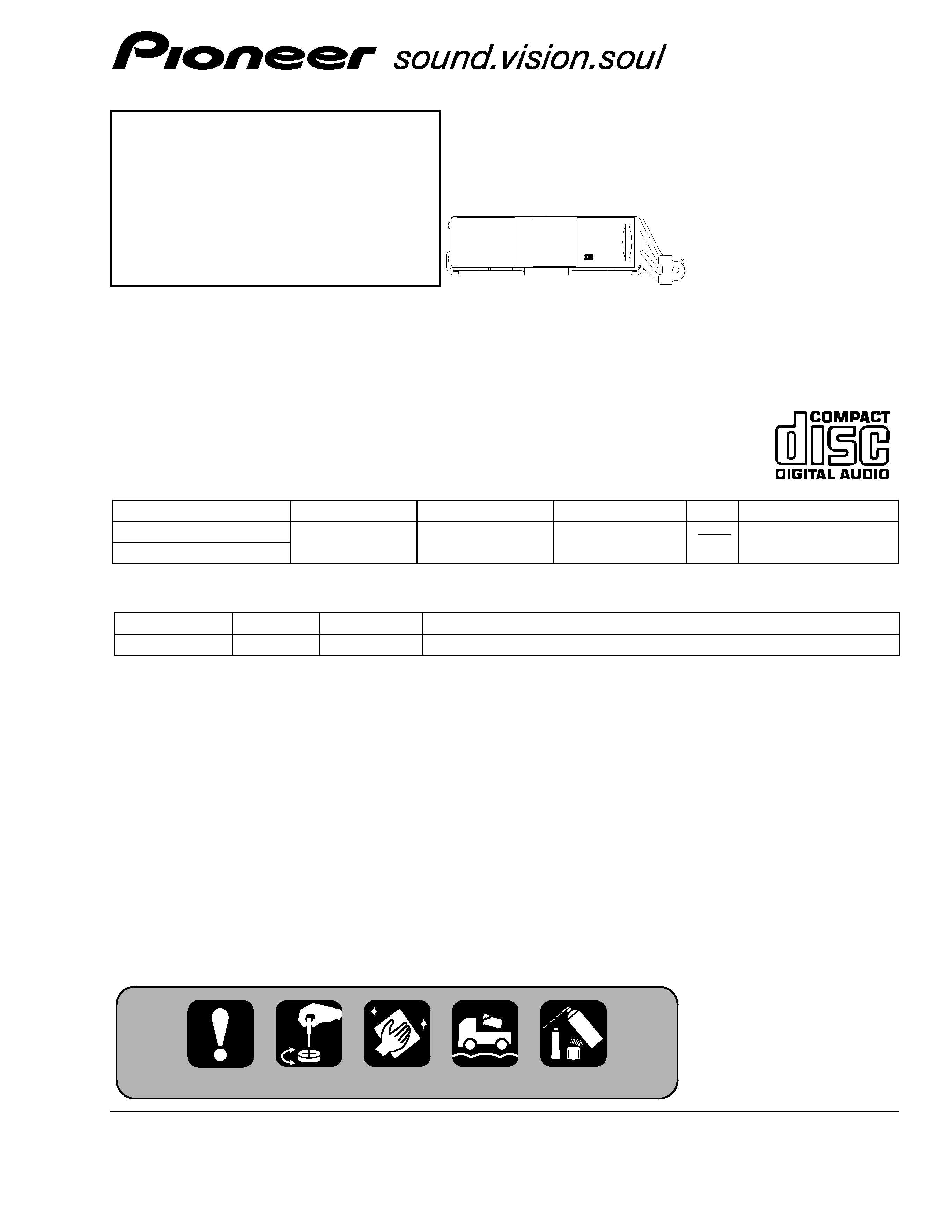
MULTI-COMPACT DISC PLAYER
CDX-M8317ZT
X1H/UC
Service
Manual
CONTENTS
1. SAFETY INFORMATION............................................3
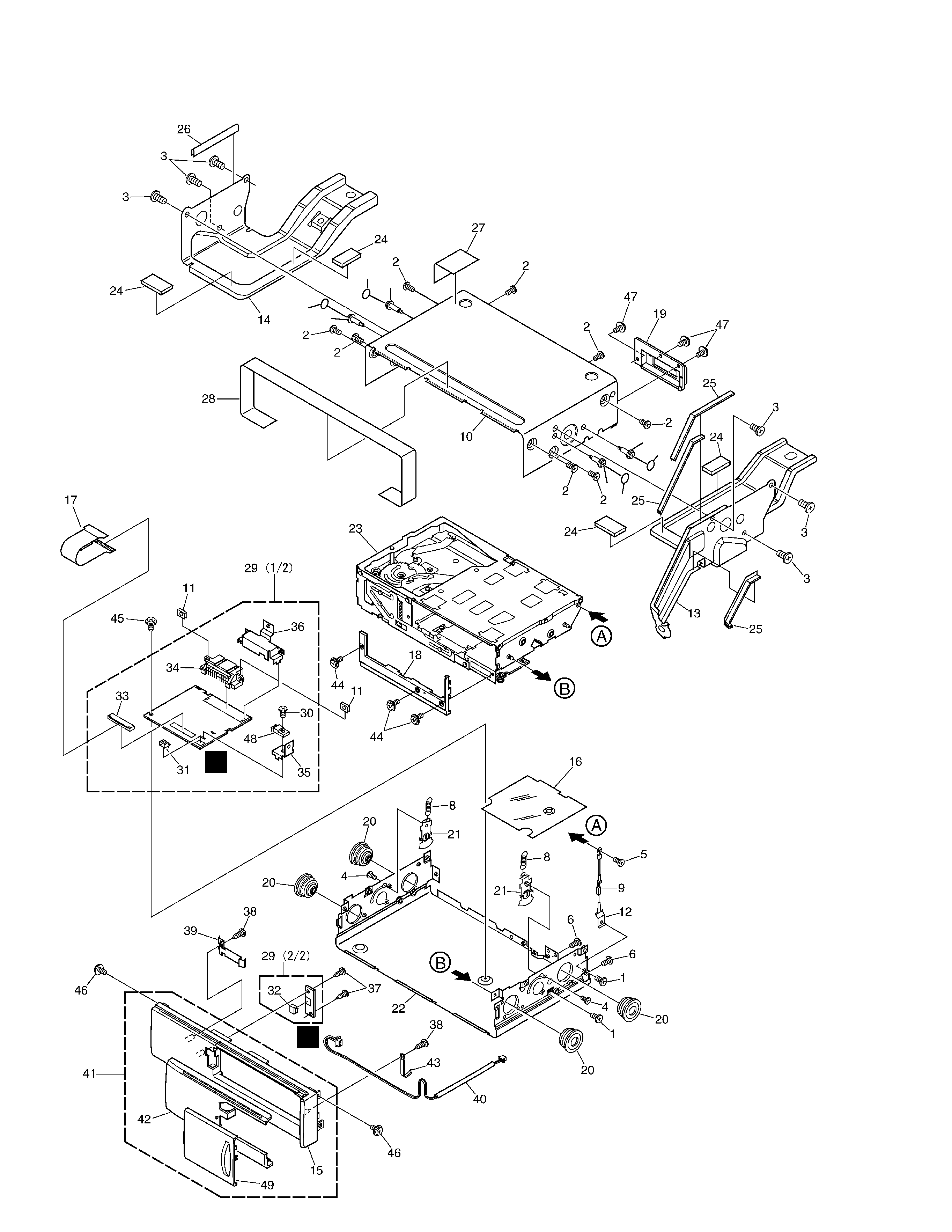
2. EXPLODED VIEWS AND PARTS LIST ......................4
3. BLOCK DIAGRAM AND SCHEMATIC DIAGRAM ....8
4. PCB CONNECTION DIAGRAM................................22
5. ELECTRICAL PARTS LIST........................................28
6. ADJUSTMENT .........................................................31
7. GENERAL INFORMATION.......................................40
7.1 DIAGNOSIS .......................................................40
7.1.1 DISASSEMBLY .............................................40
7.1.2 CONNECTOR FUNCTION DESCRIPTION ...43
7.2 IC ........................................................................44
7.3 EXPLANATION ..................................................46
7.3.1 OPERATIONAL FLOW CHART .....................46
7.3.2 SYSTEM BLOCK DIAGRAM ........................47
7.4 NOTES ON SERVICING ....................................47
7.4.1 CLEANING ....................................................47
7.4.2 FACTORY SETTINGS ...................................47
8. OPERATIONS AND SPECIFICATIONS ....................48
For details, refer to "Important symbols for good services".
VEHICLE
DESTINATION
PRODUCED AFTER TOYOTA PART No. ID No. PIONEER MODEL No.
TOYOTA:MATRIX
U.S.A., CANADA
January 2002
86270-01010
CDX-M8317ZT/X1H/UC
GM:PONTIAC VIB
- This service manual should be used together with the following manual(s):
Model No.
Order No.
Mech. Module Remarks
CX-652
CRT1857
C5
CD Mech. Module:Circuit Description, Mech.Description, Disassembly
TOYOTA