PIONEER CDX-M8067ZT/E Service Manual

Cover page of PIONEER CDX-M8067ZT/E Service Manual

Service Manual for PIONEER CDX-M8067ZT/E, downloadable as a PDF file.

We also have owner's manual to this model.

Manual details

  • Immediate download after payment.
  • Delivered as a PDF file.
  • The manual has 54 pages
  • File size: 2.21 MB
  • Available language versions: English
  • Different language versions may vary sligthly in file size and page count.

We guarantee that...

  • our manuals are complete,
  • the manual includes circuit diagrams,
  • our manuals are checked with antivirus,
  • We'll issue refund if the manual is damaged, incomplete or unreadable (our refund policy)

Sample pages

Thumbnail of page 1Thumbnail of page 2Thumbnail of page 3Thumbnail of page 4
Thumbnail of page 5Thumbnail of page 6Thumbnail of page 7Thumbnail of page 8
Thumbnail of page 9
background image
ORDER NO.
CRT2711
PUB. NO.
CRT2711
AUDIO SYSTEM
CD CHANGER
Manufactured for TOYOTA
by PIONEER CORPORATION
VEHICLE
DESTINATION
PRODUCED AFTER
TOYOTA PART No.
ID No.
PIONEER MODEL No.
LEXUS ES300
U.S.A., AUSTRALIA
July 2001
86270-33090
CDX-M8067ZT/E
ES300
Service
Manual
background image
ORDER NO.
CRT2711
PUB. NO.
CRT2711
AUDIO SYSTEM
CD CHANGER
Manufactured for TOYOTA
by PIONEER CORPORATION
VEHICLE
DESTINATION
PRODUCED AFTER
TOYOTA PART No.
ID No.
PIONEER MODEL No.
LEXUS ES300
U.S.A., AUSTRALIA
July 2001
86270-33090
CDX-M8067ZT/E
ES300
Service
Manual
background image
2
CDX-M8067ZT
CDX-M8067ZT/E
CONTENTS
1. SAFETY INFORMATION ............................................3
2. EXPLODED VIEWS AND PARTS LIST .......................4
3. BLOCK DIAGRAM AND SCHEMATIC DIAGRAM ...10
4. PCB CONNECTION DIAGRAM ................................20
5. ELECTRICAL PARTS LIST ........................................26
6. ADJUSTMENT..........................................................29
7. GENERAL INFORMATION .......................................37
7.1 DIAGNOSIS .......................................................37
7.1.1 TEST MODE.............................................37
7.1.2 DIAGNOSIS CODE TABLE ......................41
7.1.3 DISASSEMBLY ........................................46
7.1.4 CONNECTOR FUNCTION DESCRIPTION ..48
7.2 IC ........................................................................49
7.3 EXPLANATION..................................................51
7.3.1 OPERATIONAL FLOW CHART ................51
7.3.2 SYSTEM BLOCK DIAGRAM ...................52
8. OPERATIONS AND SPECIFICATIONS.....................52
- This service manual should be used together with the following manual(s):
Model No.
Order No.
Mech. Module Remarks
CX-652
CRT1857
C5
CD Mech. Module:Circuit Description, Mech.Description, Disassembly
background image
3
CDX-M8067ZT
- CD Player Service Precautions
1. For pickup unit(CXX1235) handling, please refer
to"Disassembly"(see page 46).
During replacement, handling precautions shall be
taken to prevent an electrostatic discharge(protection
by a short pin).
2. During disassembly, be sure to turn the power off
since an internal IC might be destroyed when a con-
nector is plugged or unplugged.
3. Please checking the grating after changing the ser-
vice pickup unit(see page 31).
4. The doors CAT2248 and CAT2305 have been engaged
each other tightly. When you have to replace the
door CAT2248 or CAT2305, remove both doors from
the Grille to replace them at the same time.
1. SAFETY INFORMATION
This service manual is intended for qualified service technicians; it is not meant for the casual do-it-yourselfer.
Qualified technicians have the necessary test equipment and tools, and have been trained to properly and safely repair
complex products such as those covered by this manual.
Improperly performed repairs can adversely affect the safety and reliability of the product and may void the warranty.
If you are not qualified to perform the repair of this product properly and safely, you should not risk trying to do so
and refer the repair to a qualified service technician.
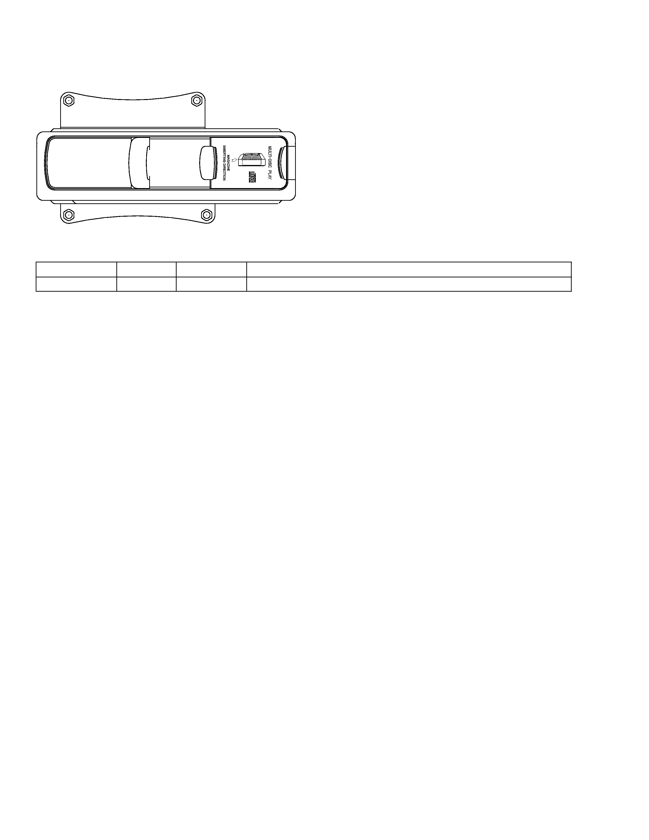
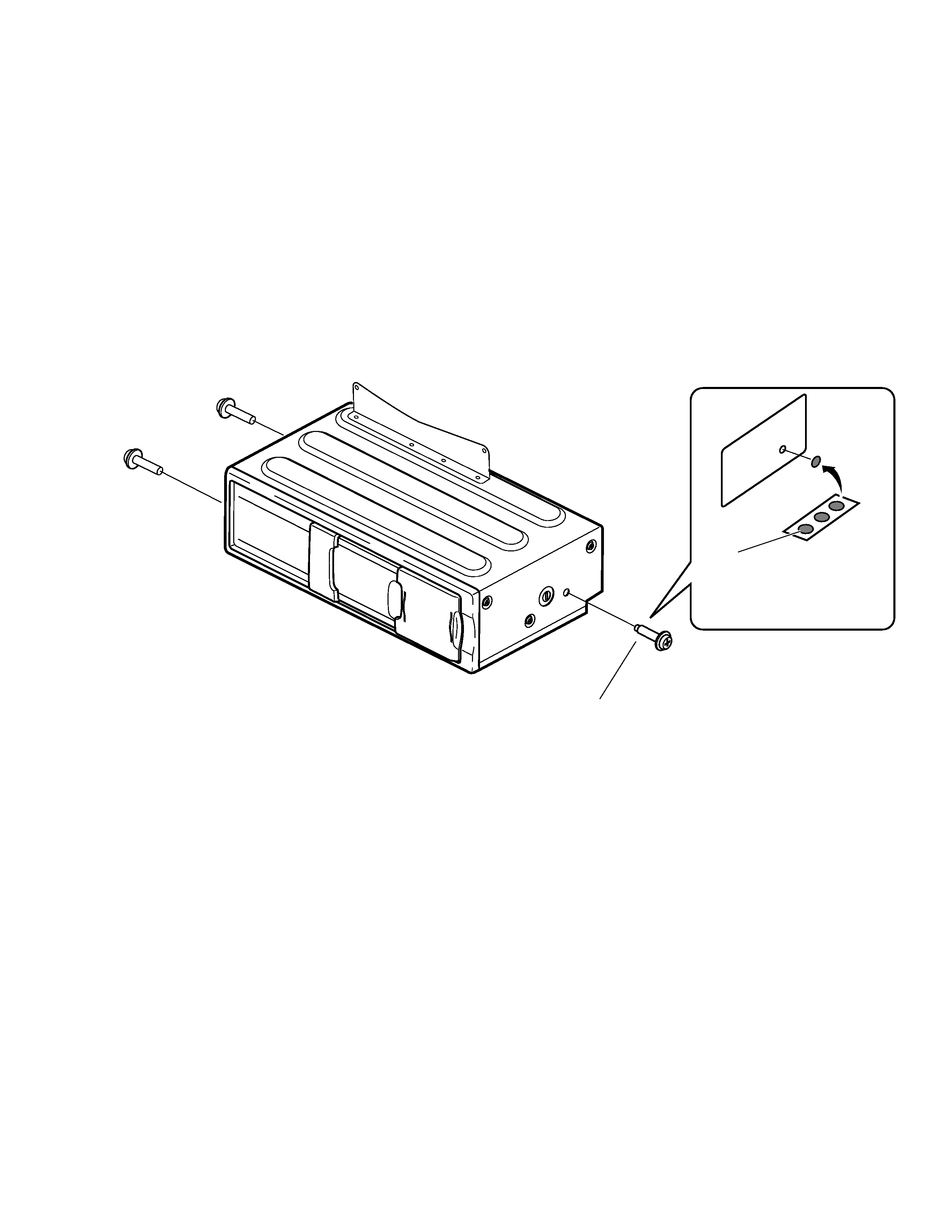
Seal
After removing transport screw,
cover the hole with the supplied
seal.
Transport screw
Attach to original position before
transporting the set.
- Transportation of multi-CD player
A transport screw has been attached to the set in order to protect it
during transportation. After removing the transport screw, cover the
hole with the supplied seal.Be sure to remove the transport screw
before mounting the set. The removed transport screw should be
retained in the accessory bag for use the next time the set is trans-
ported.
background image
4
CDX-M8067ZT
19
17
16
18
15
14
13
12
9
6
5
4
3
2
1
7
8
10
11
2. EXPLODED VIEWS AND PARTS LIST
2.1 PACKING
NOTE:
- Parts marked by "*"are generally unavailable because they are not in our Master Spare Parts List.
- Screws adjacent to
mark on the product are used for disassembly.
*
1 Polyethylene Bag
CEG1171
2 93269-15014
CBA1564
3 91626-60818
CBA1563
4 90153-50010
CBA1566
5 91635-60616
CBA1565
6 Protector
CHP2481
7-1 Owner's Manual
CRD3463
(English,French)
7-2 Polyethylene Bag
CEG1116
8-1 Installation Manual
CRD3484
(English)
8-2 Polyethylene Bag
CEG1116
9 Magazine Assy
CXB5850
10 86274-33220
CNC9747
11 86274-33210
CNC9746
12 Protector
CHP2482
13 Protector
CHP2376
14 Protector
CHP2485
15 Polyethylene Bag
CEG1174
16 Protector
CHP2483
17 Protector
CHP2484
18 Carton
CHA3219
19 Contain Box
CHL4517
Mark No. Description
Part No.
Mark No. Description
Part No.
- PACKING SECTION PARTS LIST
background image
5
CDX-M8067ZT
2.2 MAGAZINE ASSY
2
3
4
4
4
4
4
4
1
*
1 PP Case
CNS6059
*
2 Owner's Manual
CRD3236
*
3 Label
CRW1365
4 Tray Unit
CXB5983
- MAGAZINE ASSY SECTION PARTS LIST
Mark No. Description
Part No.

Reviews

There are no reviews of this manual yet.