PIONEER ELECTRONIC CORPORATION
4-1, Meguro 1-Chome, Meguro-ku, Tokyo 153-8654, Japan
PIONEER ELECTRONICS SERVICE INC.
P.O.Box 1760, Long Beach, CA 90801-1760 U.S.A.
PIONEER ELECTRONIC [EUROPE] N.V.
Haven 1087 Keetberglaan 1, 9120 Melsele, Belgium
PIONEER ELECTRONICS ASIACENTRE PTE.LTD. 253 Alexandra Road, #04-01, Singapore 159936
C PIONEER ELECTRONIC CORPORATION 1999
K-ZZY. FEB. 1999 Printed in Japan
ORDER NO.
CRT2316
UNIVERSAL MULTI-CD SYSTEM
CDX-FM657
X1N/UC
Service
Manual
CONTENTS
1. SAFETY INFORMATION ............................................3
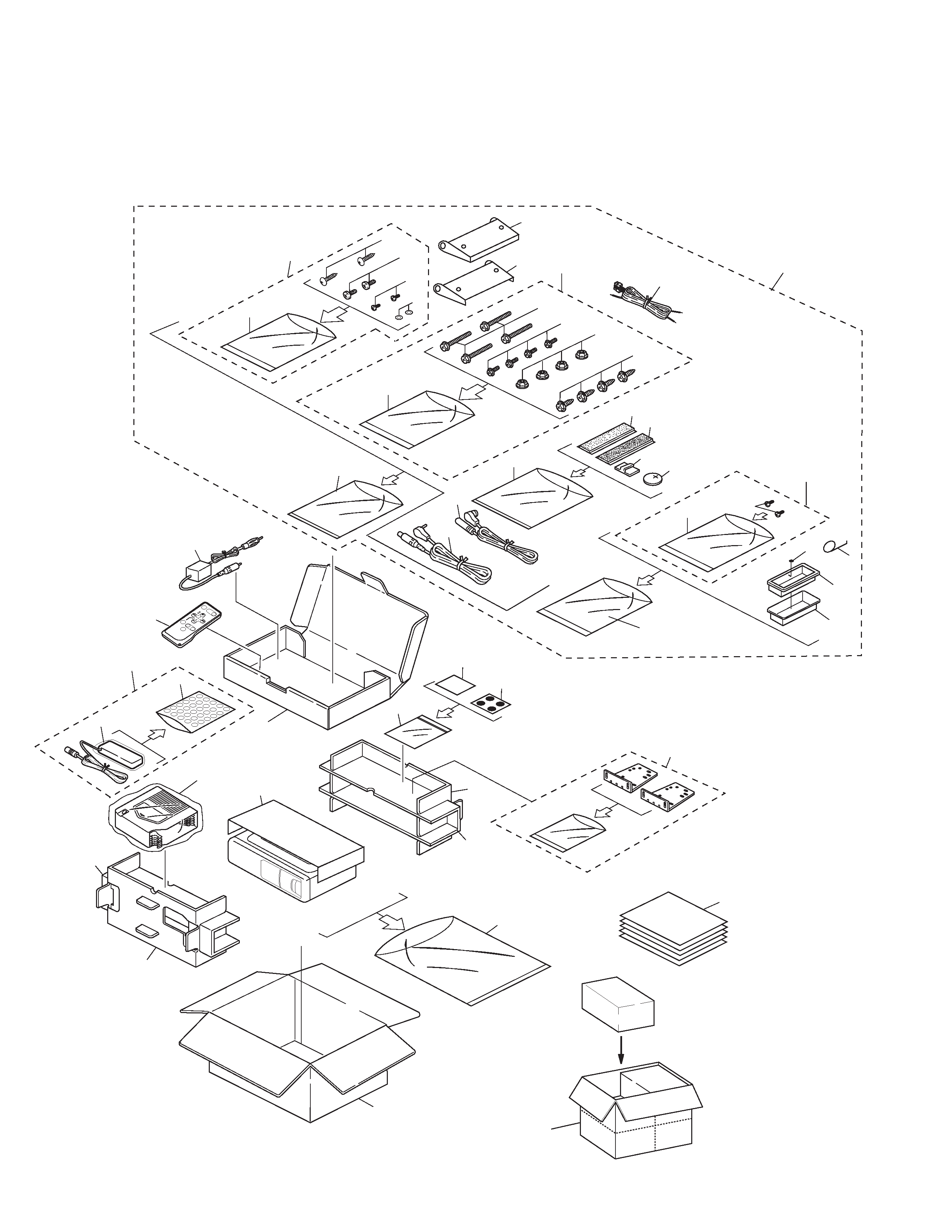
2. EXPLODED VIEWS AND PARTS LIST .......................4
3. SCHEMATIC DIAGRAM ...........................................14
4. PCB CONNECTION DIAGRAM ................................26
5. ELECTRICAL PARTS LIST ........................................34
6. ADJUSTMENT..........................................................38
7. GENERAL INFORMATION .......................................45
7.1 PARTS .................................................................45
7.1.1 IC................................................................45
7.1.2 DISPLAY ....................................................51
7.2 DIAGNOSIS ........................................................52
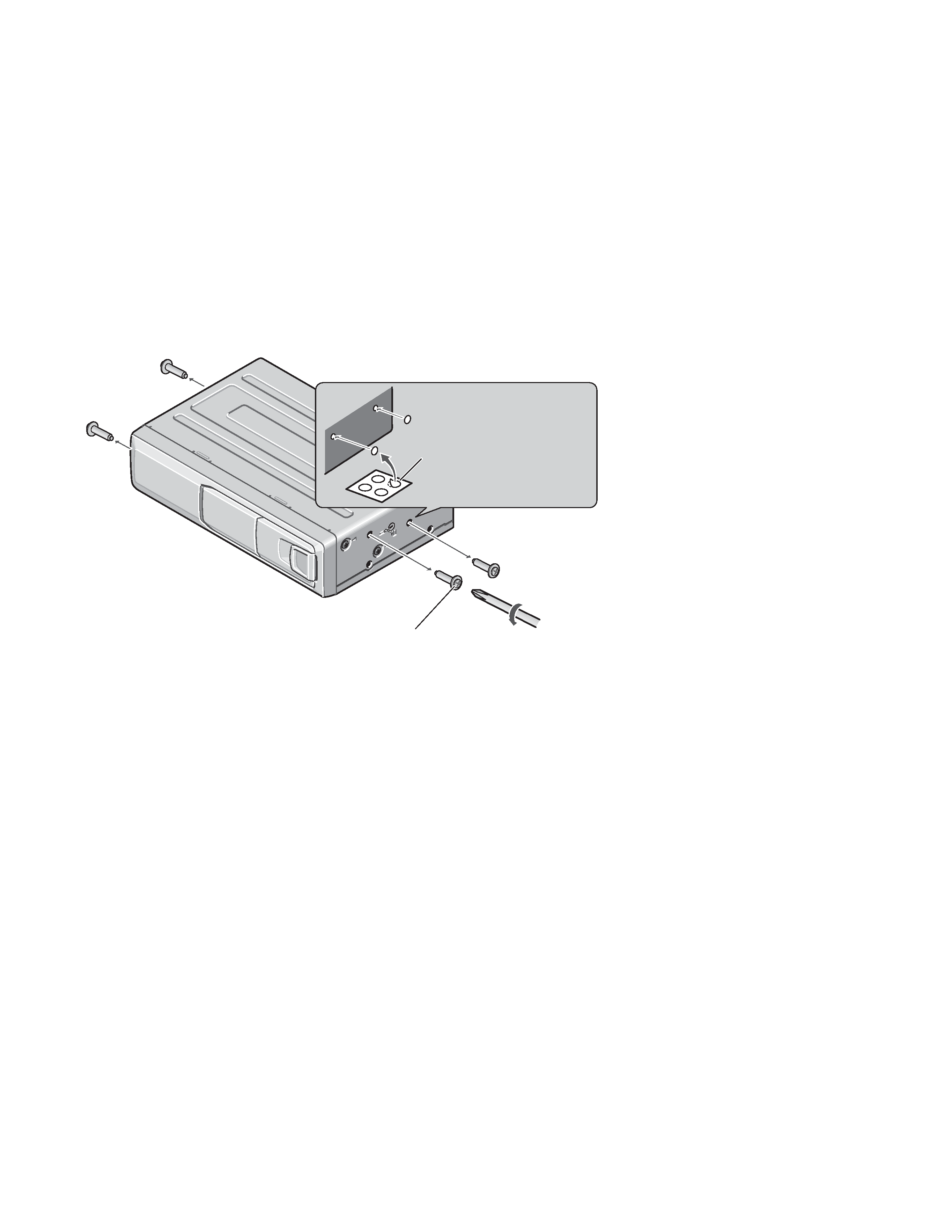
7.2.1 DISASSEMBLY .........................................52
7.2.2 TEST MODE ..............................................54
7.3 BLOCK DIAGRAM ..............................................60
8. OPERATIONS AND SPECIFICATIONS.....................62
- See the separate manual CX-892(CRT2356) for the CD mechanism description, disassembly and circuit
description.
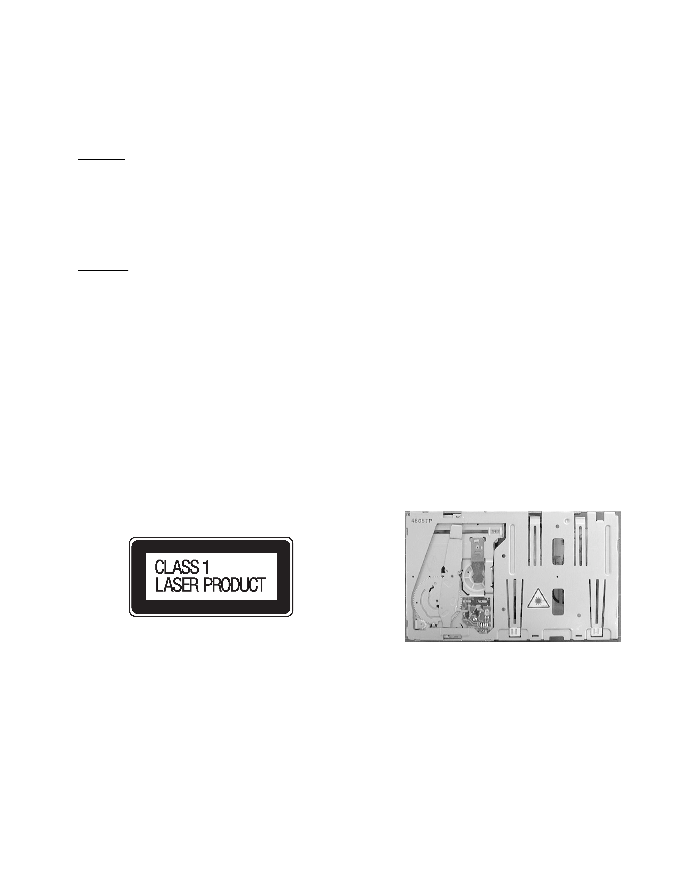
- The CD mechanism employed in this model is one of C7 series.
CDX-FM657/X1N/UC
CDX-FM657 X1N/EW
CDX-FM657 X1N/ES