PIONEER CDX-FM653 Service Manual

Cover page of PIONEER CDX-FM653 Service Manual

Service Manual for PIONEER CDX-FM653, downloadable as a PDF file.

Manual details

  • Immediate download after payment.
  • Delivered as a PDF file.
  • The manual has 62 pages
  • File size: 3.55 MB
  • Available language versions: English
  • Different language versions may vary sligthly in file size and page count.

We guarantee that...

  • our manuals are complete,
  • the manual includes circuit diagrams,
  • our manuals are checked with antivirus,
  • We'll issue refund if the manual is damaged, incomplete or unreadable (our refund policy)

Sample pages

Thumbnail of page 1Thumbnail of page 2Thumbnail of page 3Thumbnail of page 4
Thumbnail of page 5Thumbnail of page 6Thumbnail of page 7Thumbnail of page 8
Thumbnail of page 9
background image
PIONEER ELECTRONIC CORPORATION
4-1, Meguro 1-Chome, Meguro-ku, Tokyo 153-8654, Japan
PIONEER ELECTRONICS SERVICE INC.
P.O.Box 1760, Long Beach, CA 90801-1760 U.S.A.
PIONEER ELECTRONIC [EUROPE] N.V.
Haven 1087 Keetberglaan 1, 9120 Melsele, Belgium
PIONEER ELECTRONICS ASIACENTRE PTE.LTD. 253 Alexandra Road, #04-01, Singapore 159936
C PIONEER ELECTRONIC CORPORATION 1999
K-ZZY. FEB. 1999 Printed in Japan
ORDER NO.
CRT2321
UNIVERSAL MULTI-CD SYSTEM
CDX-FM653
X1N/UC
Service
Manual
CONTENTS
1. SAFETY INFORMATION ............................................2
2. EXPLODED VIEWS AND PARTS LIST .......................4
3. SCHEMATIC DIAGRAM ...........................................12
4. PCB CONNECTION DIAGRAM ................................24
5. ELECTRICAL PARTS LIST ........................................32
6. ADJUSTMENT..........................................................36
7. GENERAL INFORMATION .......................................43
7.1 PARTS .................................................................43
7.1.1 IC................................................................43
7.1.2 DISPLAY ....................................................49
7.2 DIAGNOSIS ........................................................50
7.2.1 DISASSEMBLY .........................................50
7.2.2 TEST MODE ..............................................52
7.3 BLOCK DIAGRAM ..............................................58
8. OPERATIONS AND SPECIFICATIONS.....................60
- See the separate manual CX-892(CRT2356) for the CD mechanism description, disassembly and circuit
description.
- The CD mechanism employed in this model is one of C7 series.
background image
2
CDX-FM653
- CD Player Service Precautions
1. For pickup unit(CXX1285) handling, please refer
to"Disassembly"(See page 50). During replacement,
handling precautions shall be taken to prevent an
electrostatic discharge(protection by a short pin).
2. During disassembly, be sure to turn the power off
since an internal IC might be destroyed when a con-
nector is plugged or unplugged.
3. Please checking the grating after changing the pick-
up unit (See page 37).
4 Since these screws protects the mechanism during
transport, be sure to affix it when it is transported for
repair, etc.
1. SAFETY INFORMATION
CAUTION
This service manual is intended for qualified service technicians; it is not meant for the casual do-it-yourselfer.
Qualified technicians have the necessary test equipment and tools, and have been trained to properly and safely repair
complex products such as those covered by this manual.
Improperly performed repairs can adversely affect the safety and reliability of the product and may void the warranty.
If you are not qualified to perform the repair of this product properly and safely; you should not risk trying to do so
and refer the repair to a qualified service technician.
WARNING
This product contains lead in solder and certain electrical parts contain chemicals which are known to the state of
California to cause cancer, birth defects or other reproductive harm.
Health & Safety Code Section 25249.6 - Proposition 65
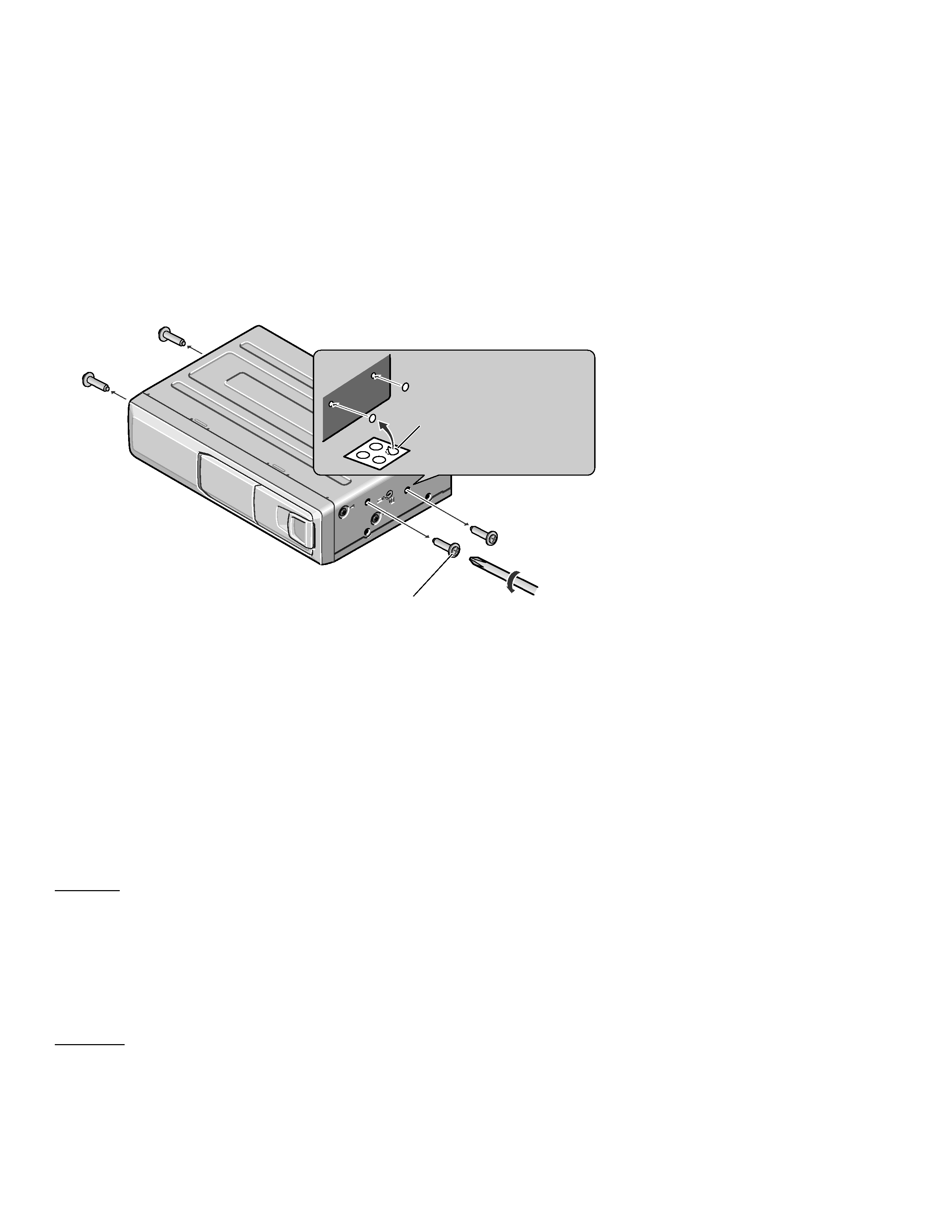
A transport screw has been attached to the
set in order to protect it during transporta-
tion. After removing the transport screw,
cover the hole with the supplied seal.
Be sure to remove the transport screw
before mounting the set. The removed
transport screw should be retained in the
accessory bag for use the next time the set
is transported.
Seal
After removing the trans-
port screw, cover the hole
with the supplied seal.
Transport screw
Attach to the original position before
transporting the set.
background image
3
CDX-FM653
background image
4
CDX-FM653
2. EXPLODED VIEWS AND PARTS LIST
2.1 PACKING
26
33
27
28
17
24
4
8
6
11
10
7
9
32
31
25
16
15
21
22
20
13
16
2
14
19
23
12
3
5
1
29
30
29
36
30
40
42
41
37
42
34
43
background image
5
CDX-FM653
- Owner's Manual
Part No.
Language
CRD2885
English, French, Spanish
- Installation Manual
Part No.
Language
CRD2886
English, French, Spanish
1 Accessory Assy
CEA2497
2 Spring
CBH-865
3 Cord
CDE4289
4 Cord
CDE5812
5 Cord
CDE5008
6 Screw Assy
CEA1962
7 Screw
CBA1295
*
8 Polyethylene Sheet
CNM5158
9 Screw
HMB60P500FMC
10 Screw
HMF40P080FZK
11 Nut
NF60FMC
12 Screw Assy
CEA1965
*
13 Polyethylene Bag
CEG-127
14 Screw
IMS30P050FZK
15 Clamper
CEF1010
*
16 Polyethylene Bag
CEG-158
17 Polyethylene Bag
CEG1185
18 ·····
19 Bracket
CNC8061
20 Cushion
CNM3182
21 Fastener(Soft)
CNM3872
22 Fastener(Rough)
CNM4041
23 Panel
CNS5428
*
24 Polyethylene Bag
CEG1099
25 Polyethylene Bag
CEG1185
26 Carton
CHG3727
27 Sub Carton
CHG3735
28 Contain Box
CHL3727
29 Protector
CHP2133
30 Protector
CHP2135
31 Seal
CNM5599
32-1 Installation Manual
CRD2886
32-2 Owner's Manual
CRD2885
* 32-3 ·····
33 Antenna Select Assy
CWM6445
34 Display Assy
CXB3249
35 ·····
36 Magazine Assy
CXB4027
37 Angle Assy
CXB3591
38 ·····
39 ·····
*
40 Caution Card
CRP1195
41 Air Cushioned Bag
CEG1055
*
42 Caution Card
CRP1090
43 Cover
CEG1062
Mark No. Description
Part No.
Mark No. Description
Part No.
- PACKING SECTION PARTS LIST
NOTE:
- Parts marked by "*" are generally unavailable because they are not in our Master Spare Parts List.
- Screws adjacent to
mark on the product are used for disassembly.

Reviews

There are no reviews of this manual yet.