3
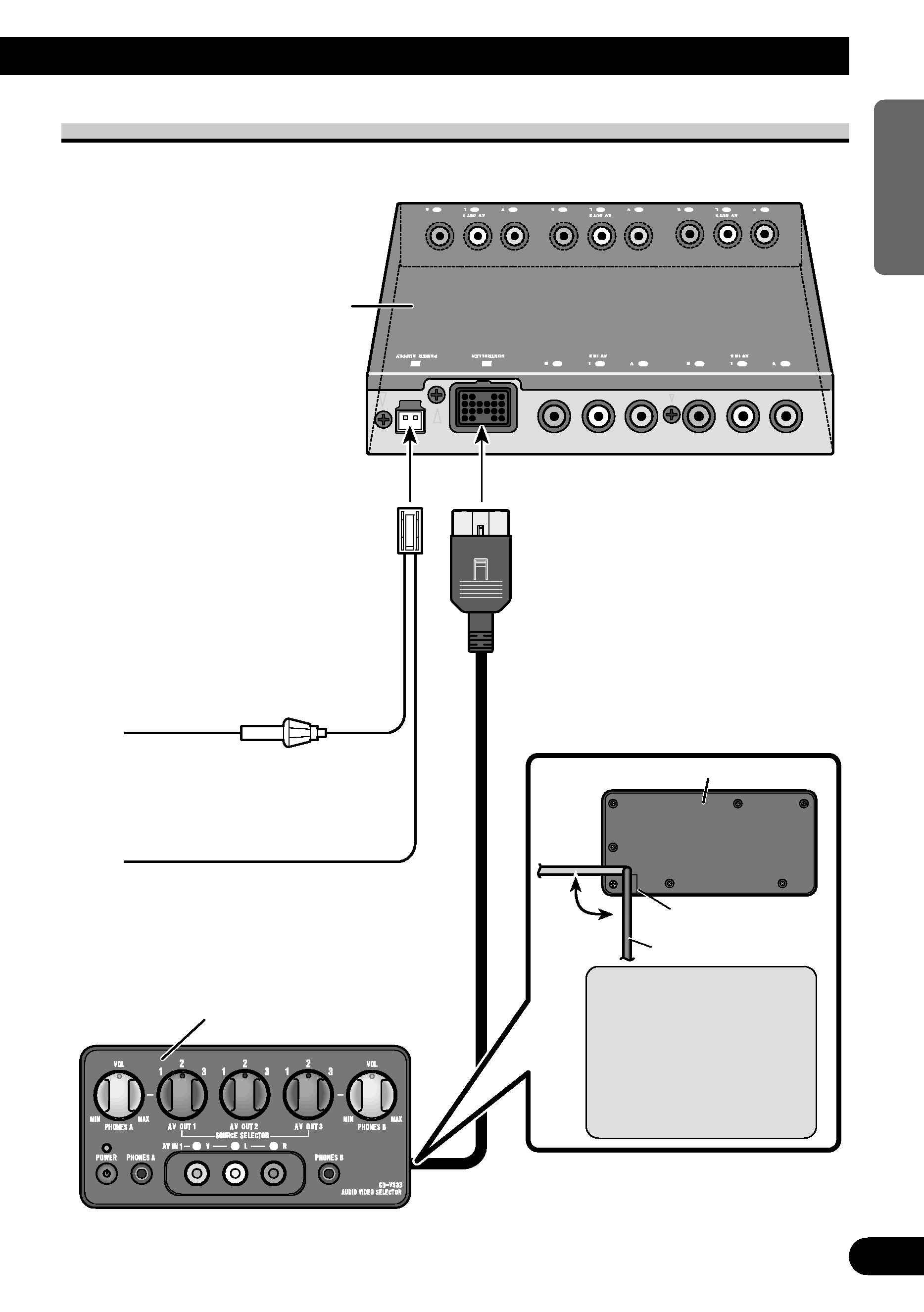
Connecting the Units
Note:
· This product is for vehicles with a 12-volt battery and negative grounding. Before installing it in a
recreational vehicle, truck, or bus, check the battery voltage.
· To avoid shorts in the electrical system, be sure to disconnect the battery cable before beginning
installation.
· After completing installation and wiring, double check that there are no mistakes. Re-install any
parts removed from the car during installation, then connect the battery negative terminal.
· Refer to the owner's manual for details on connecting the various cords of the
power amp and other units, then make connections correctly.
· Secure the wiring with cable clamps or adhesive tape. To protect the wiring, wrap adhesive tape
around them where they lie against metal parts.
· Route and secure all wiring so it cannot touch any moving parts, such as the gear shift, handbrake
and seat rails. Do not route wiring in places that get hot, such as near the heater outlet. If the
insulation of the wiring melts or gets torn, there is a danger of the wiring short-circuiting to the
vehicle body.
· Do not shorten any leads. If you do, the protection circuit may fail to work when it should.
· Never feed power to other equipment by cutting the insulation of the power supply lead of the unit
and tapping into the lead. The current capacity of the lead will be exceeded, causing overheating.
· When replacing a fuse, be sure to use only a fuse of the rating prescribed on the fuse holder.
· Always grip the Controller unit when connecting an RCA pin plug.