PIONEER CDJ-400/KUCXJ Service Manual

Cover page of PIONEER CDJ-400/KUCXJ Service Manual

Service Manual for PIONEER CDJ-400/KUCXJ, downloadable as a PDF file.

We also have owner's manual to this model.

Manual details

  • Immediate download after payment.
  • Delivered as a PDF file.
  • The manual has 87 pages
  • File size: 13.24 MB
  • Available language versions: English
  • Different language versions may vary sligthly in file size and page count.

We guarantee that...

  • our manuals are complete,
  • the manual includes circuit diagrams,
  • our manuals are checked with antivirus,
  • We'll issue refund if the manual is damaged, incomplete or unreadable (our refund policy)

Sample pages

Thumbnail of page 1Thumbnail of page 2Thumbnail of page 3Thumbnail of page 4
Thumbnail of page 5Thumbnail of page 6Thumbnail of page 7Thumbnail of page 8
Thumbnail of page 9
background image
ORDER NO.
PIONEER CORPORATION 4-1, Meguro 1-chome, Meguro-ku, Tokyo 153-8654, Japan
PIONEER ELECTRONICS (USA) INC. P.O. Box 1760, Long Beach, CA 90801-1760, U.S.A.
PIONEER EUROPE NV Haven 1087, Keetberglaan 1, 9120 Melsele, Belgium
PIONEER ELECTRONICS ASIACENTRE PTE. LTD. 253 Alexandra Road, #04-01, Singapore 159936
PIONEER CORPORATION 2007
POWER
SOURCE SELECT
DIRECTION
JOG MODE
TRACK SEARCH
SEARCH
PLAY/PAUSE
REV
FWD
0
L
Y
N
I
V
P
O
O
L
V
E
R
CUE
USB
CD
SELECT PUSH
MEMORY
DELETE
EJECT
CALL
CUE/LOOP
CDJ-400
OFF
TIME
MODE
MEMORY PC
AUTO
CUE
TEXT
MODE
UTILITY
MODE
SCRATCH
JOG EFFECT
BUBBLE
TRANS
BACK
HOLD
TEMPO
±±
±
6
10
16
WIDE
MASTERTEMPO
TEMPO
JET
ROLL
WAH
WAH
DIGITAL
JOG BREAK
REALTIME CUE
IN
OUT
RELOOP/EXIT
BEAT LOOP
LOOP DIVIDE
OUT ADJUST
HOT LOOP
ON
MULTI PLAYER
CDJ-400
RRV3679
COMPACT DISC PLAYER
CDJ-400
THIS MANUAL IS APPLICABLE TO THE FOLLOWING MODEL(S) AND TYPE(S).
Model
Type
Power Requirement
Remarks
CDJ-400
KUCXJ
AC 120 V
CDJ-400
WYXJ5
AC 220 to 240 V
CDJ-400
TLFXJ
AC 110 V to 240 V
For details, refer to "Important Check Points for good servicing".
T-ZZR NOV. 2007 printed in Japan
background image
CDJ-400
2
12
3
4
12
3
4
C
D
F
A
B
E
SAFETY INFORMATION
1. SAFETY PRECAUTIONS
The following check should be performed for the
continued protection of the customer and service
technician.
LEAKAGE CURRENT CHECK
Measure leakage current to a known earth ground
(water pipe, conduit, etc.) by connecting a leakage
current tester such as Simpson Model 229-2 or
equivalent between the earth ground and all exposed
metal parts of the appliance (input/output terminals,
screwheads, metal overlays, control shaft, etc.). Plug
the AC line cord of the appliance directly into a 120V
AC 60 Hz outlet and turn the AC power switch on. Any
current measured must not exceed 0.5 mA.
ANY
MEASUREMENTS
NOT WITHIN THE
LIMITS
OUTLINED ABOVE ARE INDICATIVE OF A POTENTIAL
SHOCK HAZARD AND MUST BE CORRECTED BEFORE
RETURNING THE APPLIANCE TO THE CUSTOMER.
2. PRODUCT SAFETY NOTICE
Many electrical and mechanical parts in the appliance
have special safety related characteristics. These are
often not evident from visual inspection nor the protection
afforded by them necessarily can be obtained by using
replacement components rated for voltage, wattage, etc.
Replacement parts which have these special safety
characteristics are identified in this Service Manual.
Electrical components having such features are
identified by marking with a
> on the schematics and on
the parts list in this Service Manual.
The use of a substitute replacement component which
does not have the same safety characteristics as the
PIONEER recommended replacement one, shown in the
parts list in this Service Manual, may create shock, fire,
or other hazards.
Product Safety is continuously under review and new
instructions are issued from time to time. For the latest
information, always consult the current PIONEER Service
Manual. A subscription to, or additional copies of,
PIONEER Service Manual may be obtained at a nominal
charge from PIONEER.
Leakage
current
tester
Reading should
not be above
0.5 mA
Device
under
test
Test all
exposed metal
surfaces
Also test with
plug reversed
(Using AC adapter
plug as required)
Earth
ground
AC Leakage Test
(FOR USA MODEL ONLY)
WARNING
This product contains lead in solder and certain electrical parts contain chemicals which are known to the state of California to
cause cancer, birth defects or other reproductive harm.
Health & Safety Code Section 25249.6 - Proposition 65
NOTICE
(FOR CANADIAN MODEL ONLY)
Fuse symbols
(fast operating fuse) and/or
(slow operating fuse) on PCB indicate that replacement parts must
be of identical designation.
REMARQUE
(POUR MODÈLE CANADIEN SEULEMENT)
Les symboles de fusible
(fusible de type rapide) et/ou
(fusible de type lent) sur CCI indiquent que les pièces
de remplacement doivent avoir la même désignation.
This service manual is intended for qualified service technicians ; it is not meant for the casual
do-it-yourselfer. Qualified technicians have the necessary test equipment and tools, and have been
trained to properly and safely repair complex products such as those covered by this manual.
Improperly performed repairs can adversely affect the safety and reliability of the product and may
void the warranty. If you are not qualified to perform the repair of this product properly and safely, you
should not risk trying to do so and refer the repair to a qualified service technician.
background image
CDJ-400
3
5
678
56
7
8
C
D
F
A
B
E
IMPORTANT
THIS PIO N EER APPARATUS CO N TA I N S
LASER OF CLASS 1.
SERVICING OPERATION OF THE APPARATUS
SHOULD BE DO N E BY A SPECIALLY
INSTRUCTED PERSON.
LASER DIODE CHARACTERISTICS
MAXIMUM OUTPUT POWER: 5 mW
WAVELENGTH: 780 ­ 785 nm
WARNING !
The AEL(accessible emission level) of the laser power output is less then CLASS 1
but the laser component is capable of emitting radiation exceeding the limit for
CLASS 1.
A specially instructed person should do servicing operation of the apparatus.
Additional Laser Caution
* : Refer to page 24.
for TLFXJ
for WYXJ5 and KUCXJ
for TLFXJ
(DRW2308)
(DRW2248)
1. Laser Interlock Mechanism
The position of the switch (S1801) for detecting loading
completion is detected by the system microprocessor,
and the design prevents laser diode oscillation when
the switch is not in LPS1 terminal side (when the
mechanism is not clamped and LPS1 signal is
high level.)
Thus, the interlock will no longer function if the switch is
deliberately set to LPS1 terminal side. ( if LPS1 signal
is low level ).
In the test mode* the interlock mechanism will not
function. Laser diode oscillation will continue, if pin 41
of TC94A15FG (IC502) on the MAIN Assy is
connected to GND, or else the terminals of Q501 are
shorted to each other (fault condition).
2. When the cover is opened, close viewing of the
objective lens with the naked eye will cause exposure
to a Class 1 laser beam.
CDJ-400 WYXJ5 and KUCXJ : Types Only
Chassis
LABEL CHECK
Printed on the chassis
background image
CDJ-400
4
12
3
4
12
3
4
C
D
F
A
B
E
[Important Check Points for Good Servicing]
In this manual, procedures that must be performed during repairs are marked with the below symbol.
Please be sure to confirm and follow these procedures.
1. Product safety
Please conform to product regulations (such as safety and radiation regulations), and maintain a safe servicing environment by
following the safety instructions described in this manual.
1 Use specified parts for repair.
Use genuine parts. Be sure to use important parts for safety.
2 Do not perform modifications without proper instructions.
Please follow the specified safety methods when modification(addition/change of parts) is required due to interferences such as
radio/TV interference and foreign noise.
3 Make sure the soldering of repaired locations is properly performed.
When you solder while repairing, please be sure that there are no cold solder and other debris.
Soldering should be finished with the proper quantity. (Refer to the example)
4 Make sure the screws are tightly fastened.
Please be sure that all screws are fastened, and that there are no loose screws.
5 Make sure each connectors are correctly inserted.
Please be sure that all connectors are inserted, and that there are no imperfect insertion.
6 Make sure the wiring cables are set to their original state.
Please replace the wiring and cables to the original state after repairs.
In addition, be sure that there are no pinched wires, etc.
7 Make sure screws and soldering scraps do not remain inside the product.
Please check that neither solder debris nor screws remain inside the product.
8 There should be no semi-broken wires, scratches, melting, etc.on the coating of the power cord.
Damaged power cords may lead to fire accidents, so please be sure that there are no damages.
If you find a damaged power cord, please exchange it with a suitable one.
9 There should be no spark traces or similar marks on the power plug.
When spark traces or similar marks are found on the power supply plug, please check the connection and advise on secure
connections and suitable usage. Please exchange the power cord if necessary.
a Safe environment should be secured during servicing.
When you perform repairs, please pay attention to static electricity, furniture, household articles, etc. in order to prevent injuries.
Please pay attention to your surroundings and repair safely.
2. Adjustments
To keep the original performance of the products, optimum adjustments and confirmation of characteristics within specification.
Adjustments should be performed in accordance with the procedures/instructions described in this manual.
4. Cleaning
For parts that require cleaning, such as optical pickups, tape deck heads, lenses and mirrors used in projection monitors, proper
cleaning should be performed to restore their performances.
3. Lubricants, Glues, and Replacement parts
Use grease and adhesives that are equal to the specified substance.
Make sure the proper amount is applied.
5. Shipping mode and Shipping screws
To protect products from damages or failures during transit, the shipping mode should be set or the shipping screws should be
installed before shipment. Please be sure to follow this method especially if it is specified in this manual.
background image
CDJ-400
5
5
678
56
7
8
C
D
F
A
B
E
CONTENTS
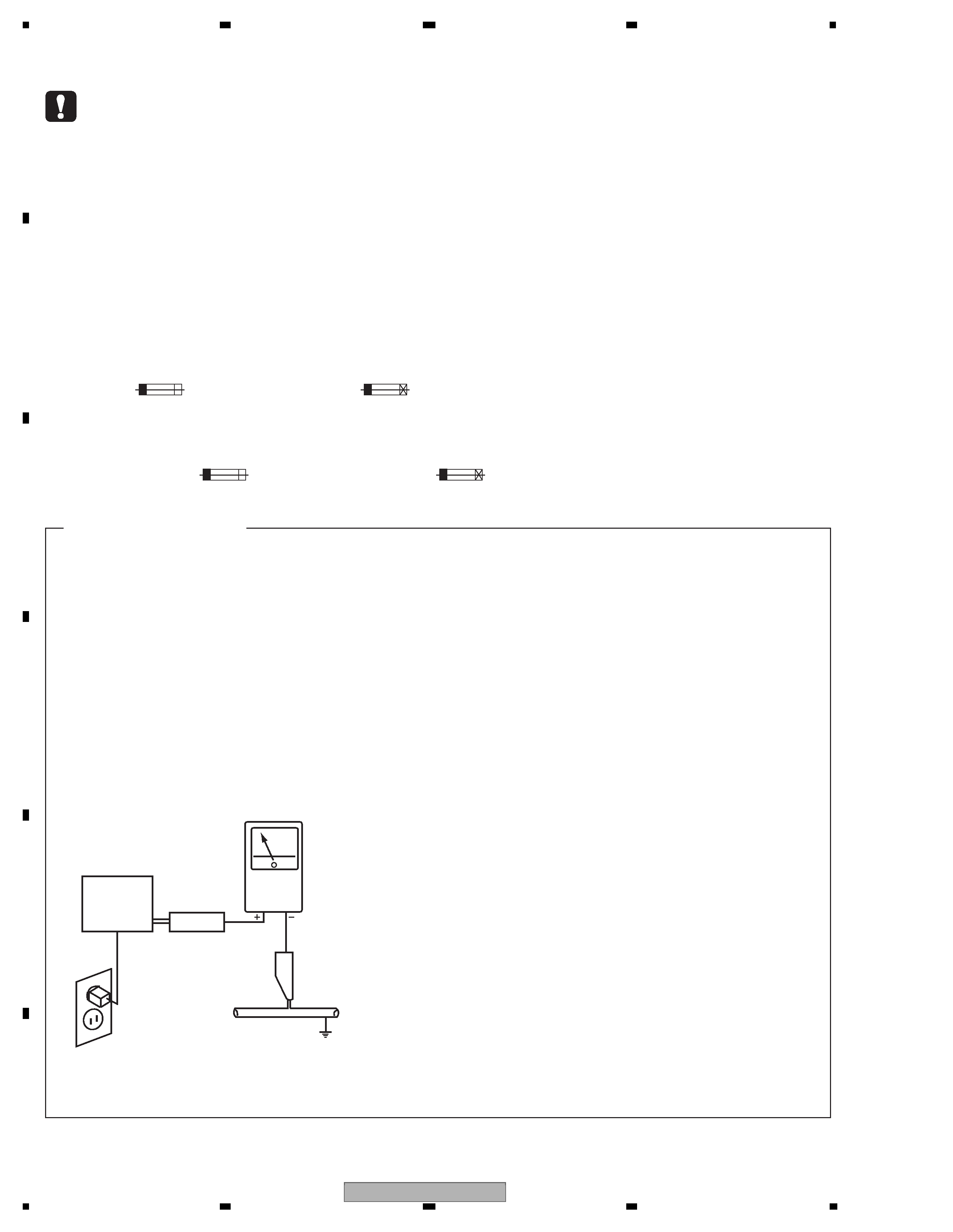
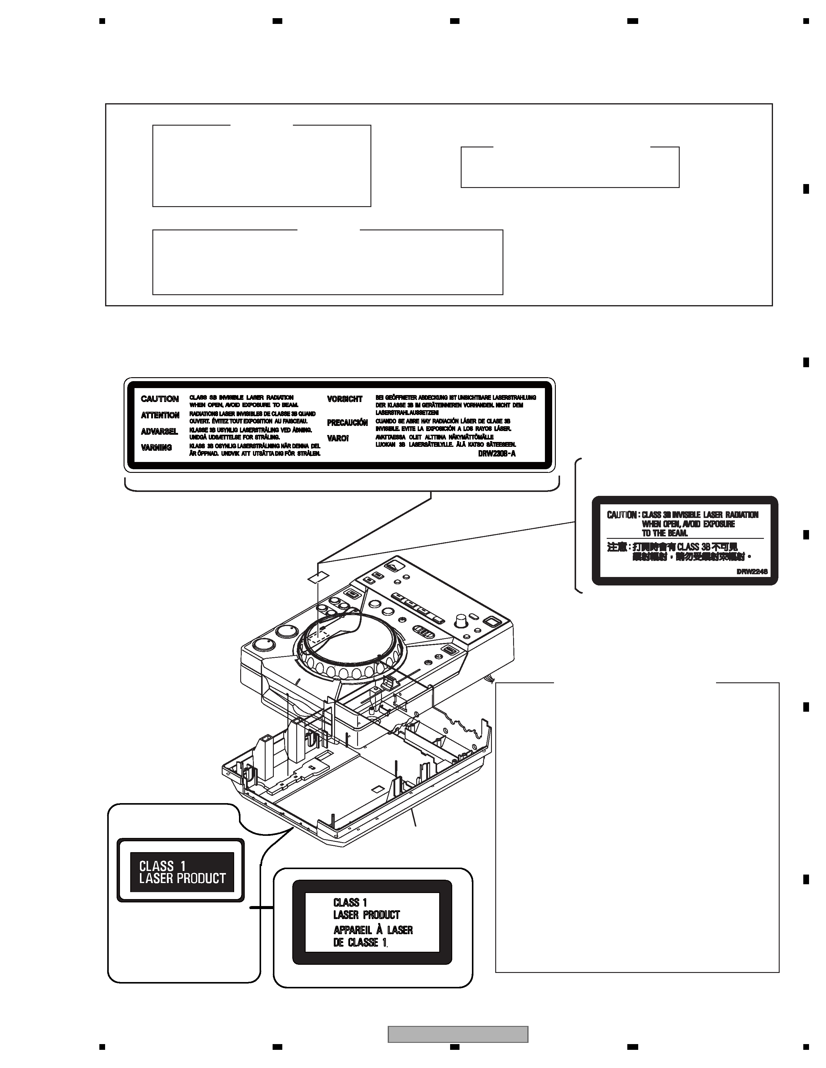
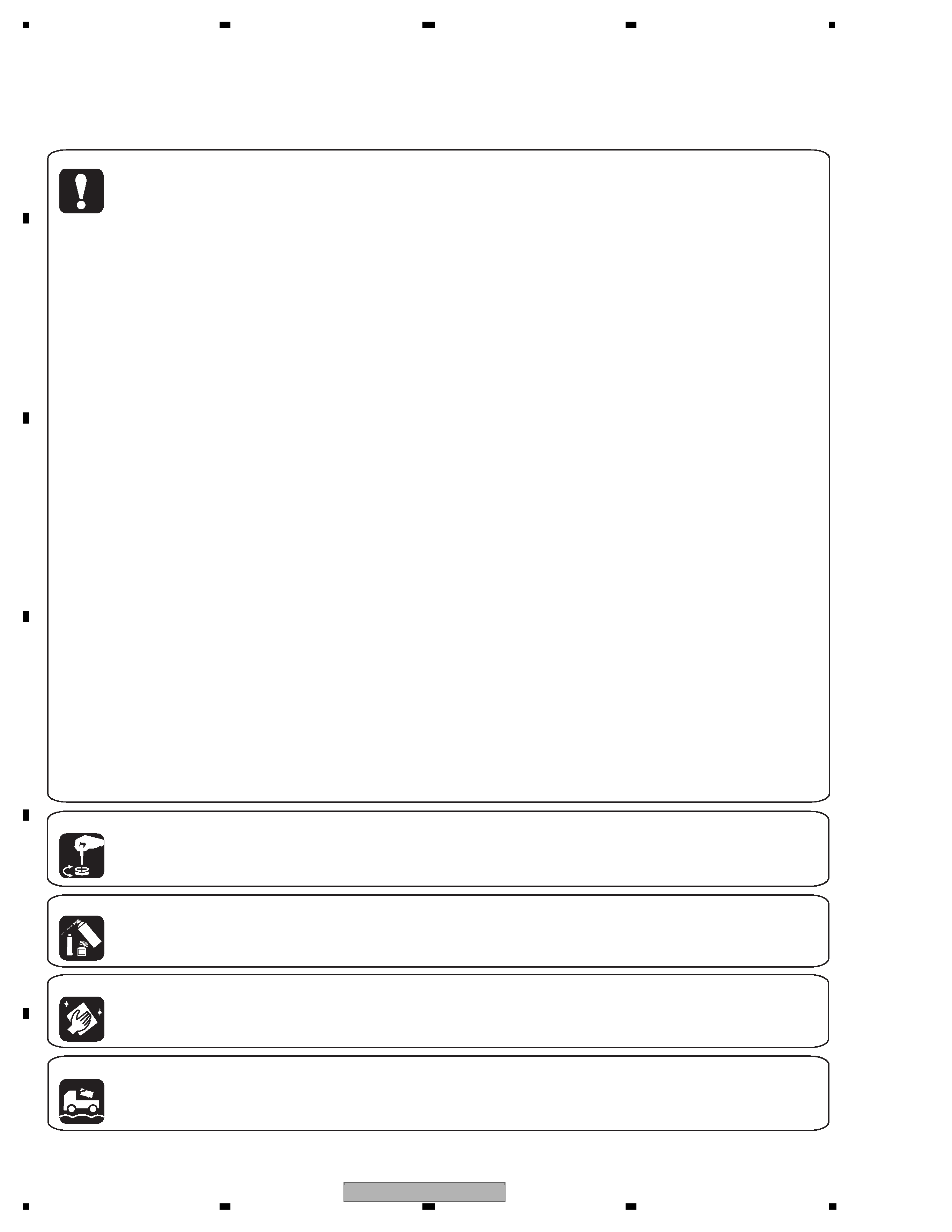
SAFETY INFORMATION .....................................................................................................................................2
1. SERVICE PRECAUTIONS ................................................................................................................................6
1.1 NOTES ON SOLDERING ...........................................................................................................................6
2. SPECIFICATIONS.............................................................................................................................................7
2.1 ACCESSORIES..........................................................................................................................................7
2.2 SPECIFICATIONS ......................................................................................................................................8
2.3 DISC USABLE WITH THIS UNIT ...............................................................................................................9
2.4 PANEL FACILITIES...................................................................................................................................11
3. BASIC ITEMS FOR SERVICE ........................................................................................................................14
3.1 CHECK POINTS AFTER SERVICING .....................................................................................................14
3.2 PCB LOCATIONS .....................................................................................................................................15
3.3 JIGS LIST .................................................................................................................................................16
4. BLOCK DIAGRAM ..........................................................................................................................................18
4.1 OVERALL WIRING DIAGRAM .................................................................................................................18
4.2 OVERALL BLOCK DIAGRAM ..................................................................................................................20
5. DIAGNOSIS ....................................................................................................................................................22
5.1 CHECKING THE PICKUP ASSY..............................................................................................................22
5.2 POWER ON SEQUENCE.........................................................................................................................23
6. SERVICE MODE .............................................................................................................................................24
6.1 OVERVIEW OF SERVICE MODE ............................................................................................................24
6.2 CHECK MODE OPERATION....................................................................................................................24
7. DISASSEMBLY ...............................................................................................................................................32
8. EACH SETTING AND ADJUSTMENT ............................................................................................................39
9. EXPLODED VIEWS AND PARTS LIST ..........................................................................................................40
9.1 PACKING SECTION .................................................................................................................................40
9.2 EXTERIOR SECTION ..............................................................................................................................42
9.3 CONTROL PANEL SECTION...................................................................................................................44
9.4 JOG DIAL SECTION ................................................................................................................................46
9.5 SLOT-IN MECHANISM SECTION ............................................................................................................48
10. SCHEMATIC DIAGRAM................................................................................................................................50
10.1 MAIN ASSY (1/2)....................................................................................................................................50
10.2 MAIN ASSY (2/2)....................................................................................................................................52
10.3 CNCT and SLMB ASSYS .......................................................................................................................54
10.4 PNLB ASSY............................................................................................................................................56
10.5 JACB ASSY ............................................................................................................................................58
10.6 REGB and ACIN ASSYS ........................................................................................................................60
10.7 JOGB, TCHB and SW POWER SUPPLY ASSYS ..................................................................................62
10.8 VOLTAGES .............................................................................................................................................64
10.9 WAVEFORMS.........................................................................................................................................66
11. PCB CONNECTION DIAGRAM ....................................................................................................................71
11.1 TCHB ASSY ...........................................................................................................................................71
11.2 MAIN, CNCT, SLMB and JACB ASSYS .................................................................................................72
11.3 PNLB ASSY............................................................................................................................................76
11.4 REGB ASSY ...........................................................................................................................................80
11.5 JOGB and ACIN ASSYS ........................................................................................................................82
12. PCB PARTS LIST..........................................................................................................................................84

Reviews

There are no reviews of this manual yet.