CONTENTS
1. SAFETY INFORMATION............................................2
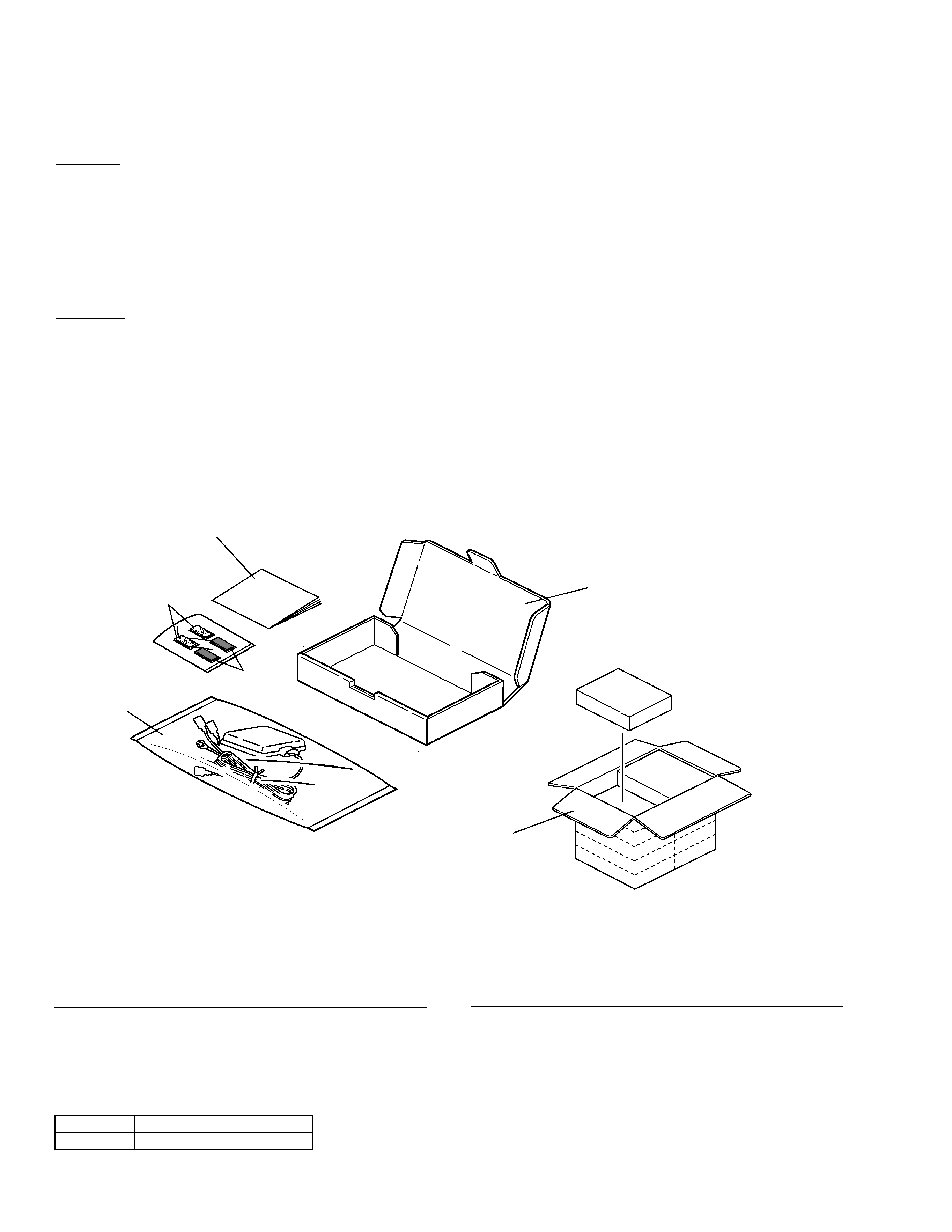
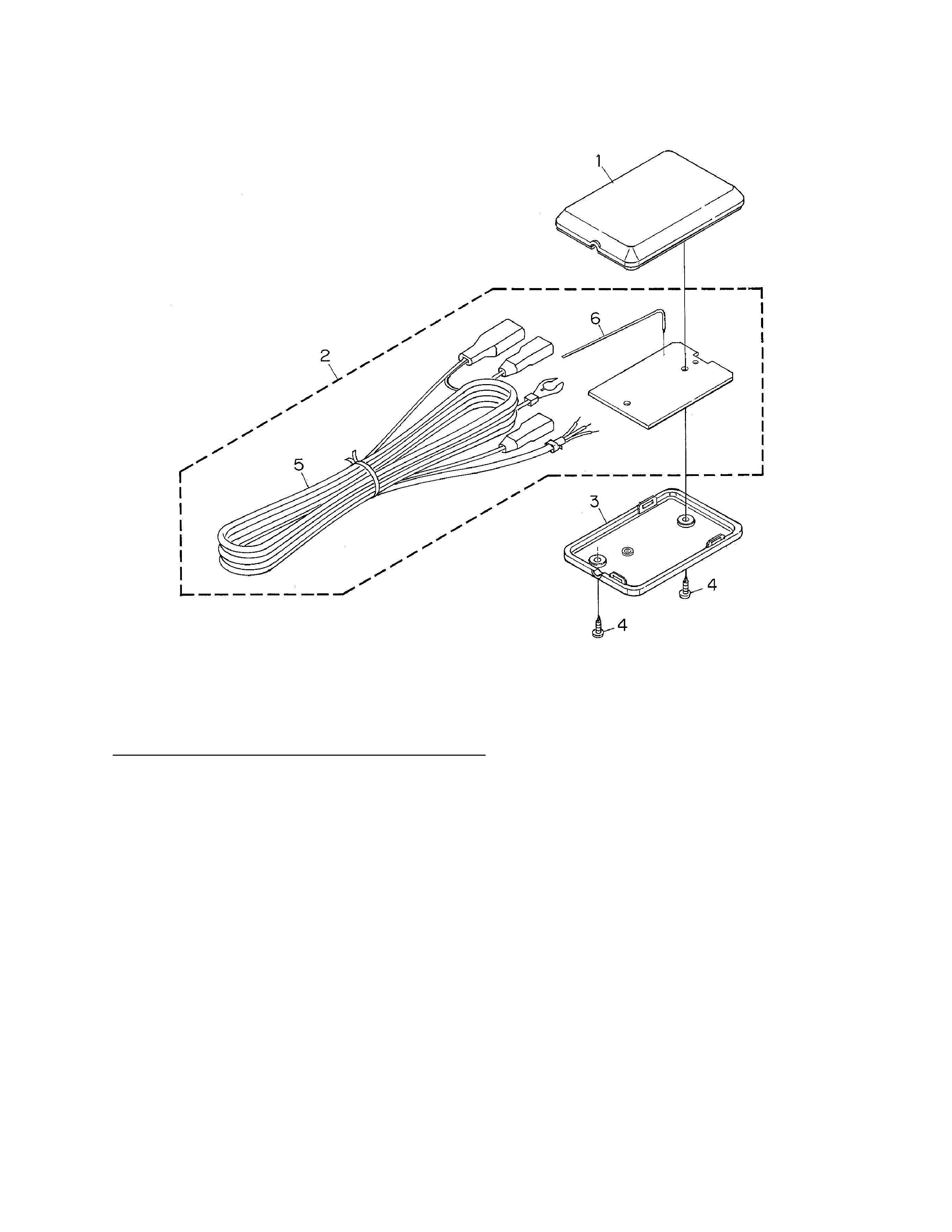
2. EXPLODED VIEWS AND PARTS LIST ......................2
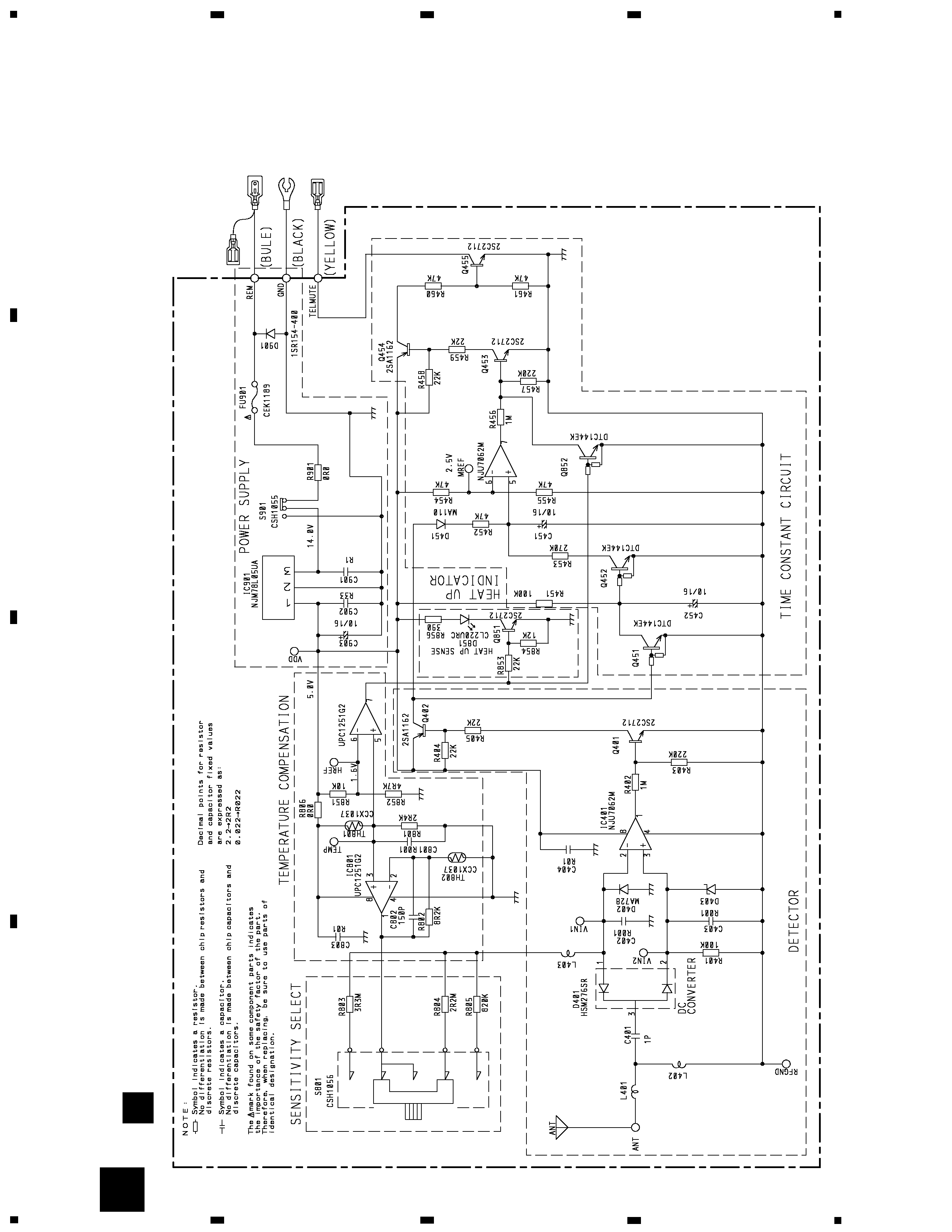
3. SCHEMATIC DIAGRAM .............................................4
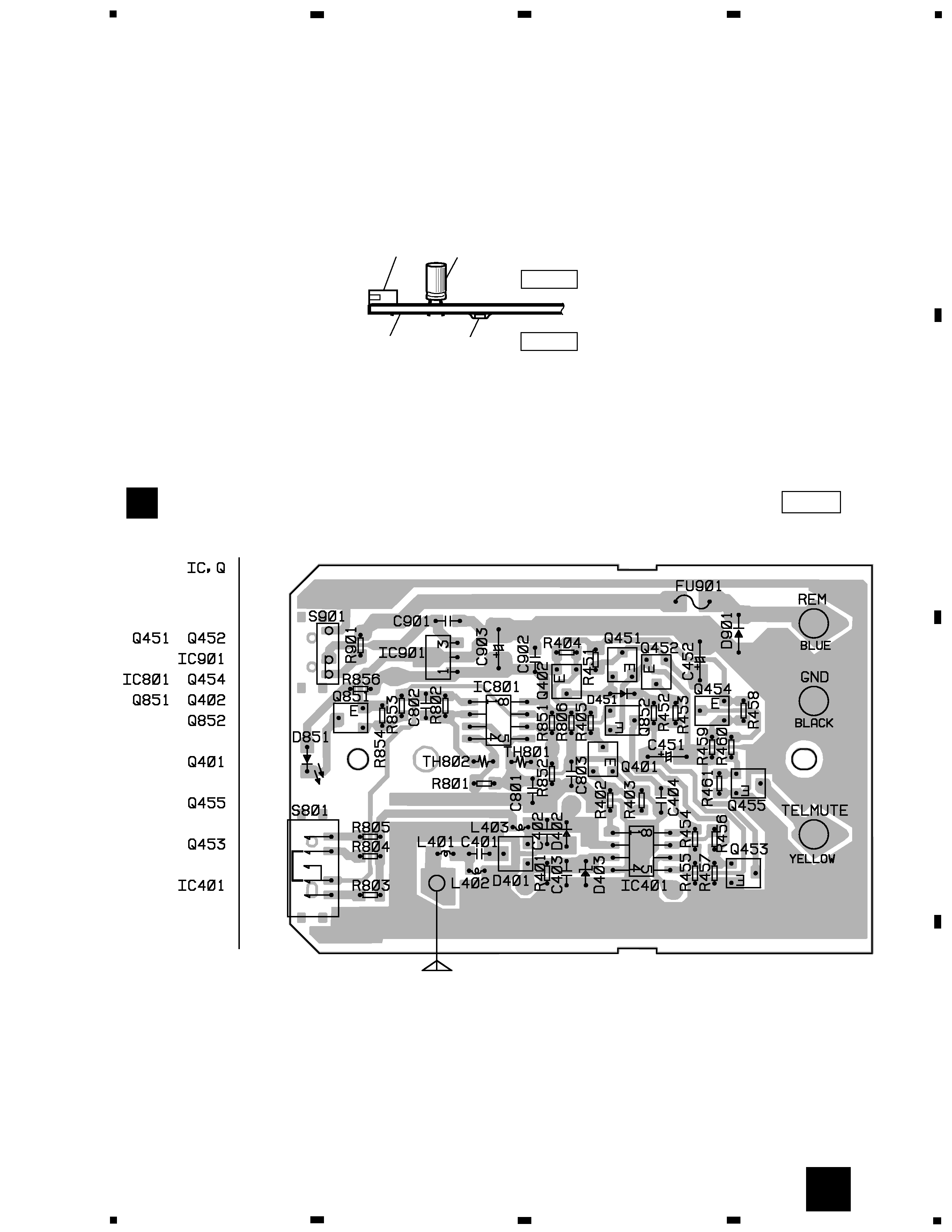
4. PCB CONNECTION DIAGRAM..................................5
5. ELECTRICAL PARTS LIST..........................................6
6. ADJUSTMENT ...........................................................6
7. GENERAL INFORMATION.........................................7
7.1 IC ..........................................................................7
8. OPERATIONS AND SPECIFICATIONS ......................8
PIONEER ELECTRONIC CORPORATION
4-1, Meguro 1-Chome, Meguro-ku, Tokyo 153-8654, Japan
PIONEER ELECTRONICS SERVICE INC.
P.O.Box 1760, Long Beach, CA 90801-1760 U.S.A.
PIONEER ELECTRONIC [EUROPE] N.V.
Haven 1087 Keetberglaan 1, 9120 Melsele, Belgium
PIONEER ELECTRONICS ASIACENTRE PTE.LTD. 253 Alexandra Road, #04-01, Singapore 159936
C PIONEER ELECTRONIC CORPORATION 1999
K-ZZB. MAR. 1999 Printed in Japan
ORDER NO.
CRT2331
WIRELESS CELLULAR MUTE KIT
CD-CM1
E
Service
Manual
NOTE:
- For the detection diode (D401: HSM276SR), the withstanding static voltage is very low. So, pay special
attention to static electricity to protect the diode from electrostatic damage when servicing.
- When the detection antenna has been removed from the upper case for servicing, be sure to stick it
onto the upper case with adhesive tape along the guide, after the repair is completed.