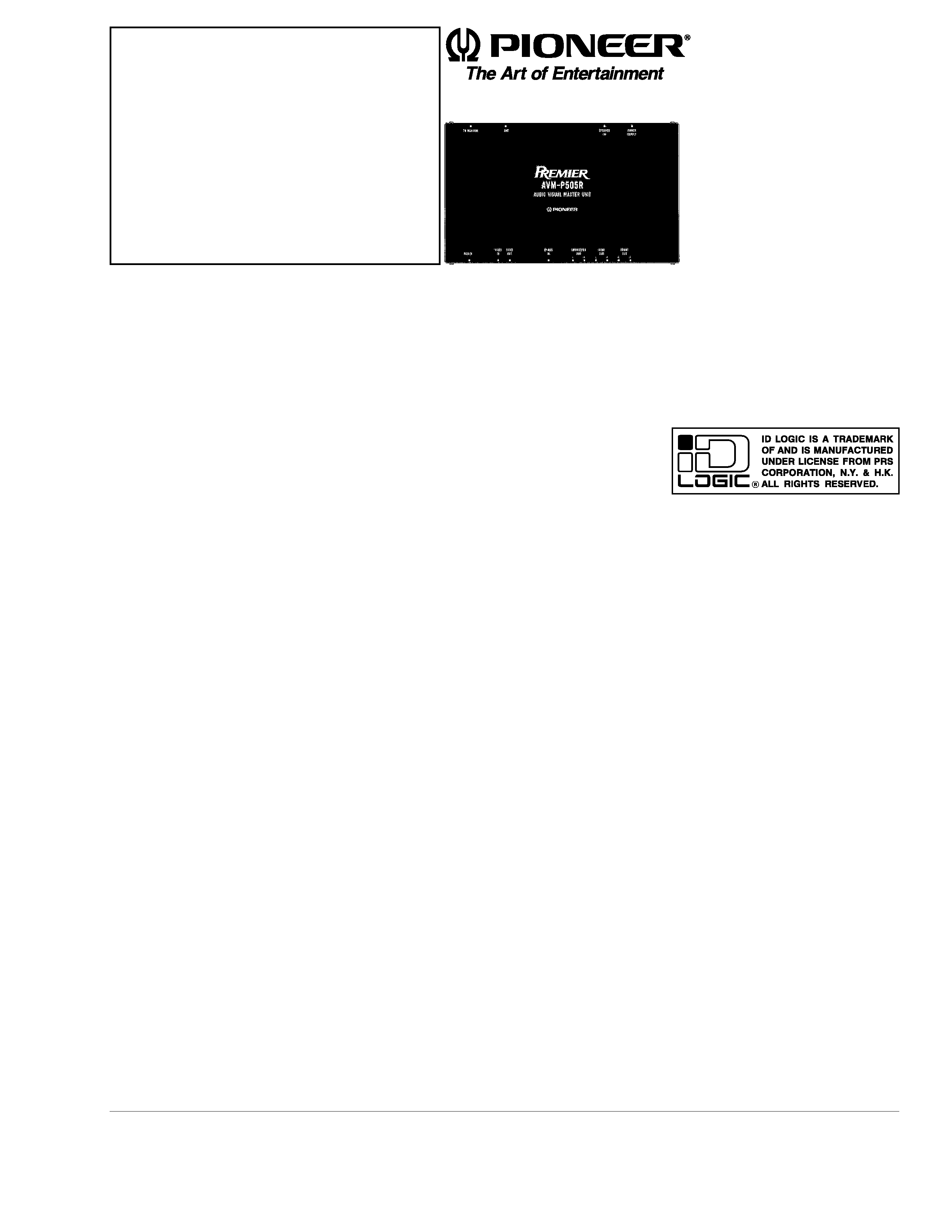
AUDIO VISUAL MASTER UNIT
AVM-P505R
UC
Service
Manual
PIONEER ELECTRONIC CORPORATION
4-1, Meguro 1-Chome, Meguro-ku, Tokyo 153-8654, Japan
PIONEER ELECTRONICS SERVICE INC.
P.O.Box 1760, Long Beach, CA 90801-1760 U.S.A.
PIONEER ELECTRONIC [EUROPE] N.V.
Haven 1087 Keetberglaan 1, 9120 Melsele, Belgium
PIONEER ELECTRONICS ASIACENTRE PTE.LTD. 501 Orchard Road, #10-00, Lane Wheelock Place, Singapore 238880
C PIONEER ELECTRONIC CORPORATION 1998
ORDER NO.
CRT2215
CONTENTS
1. SAFETY INFORMATION ............................................2
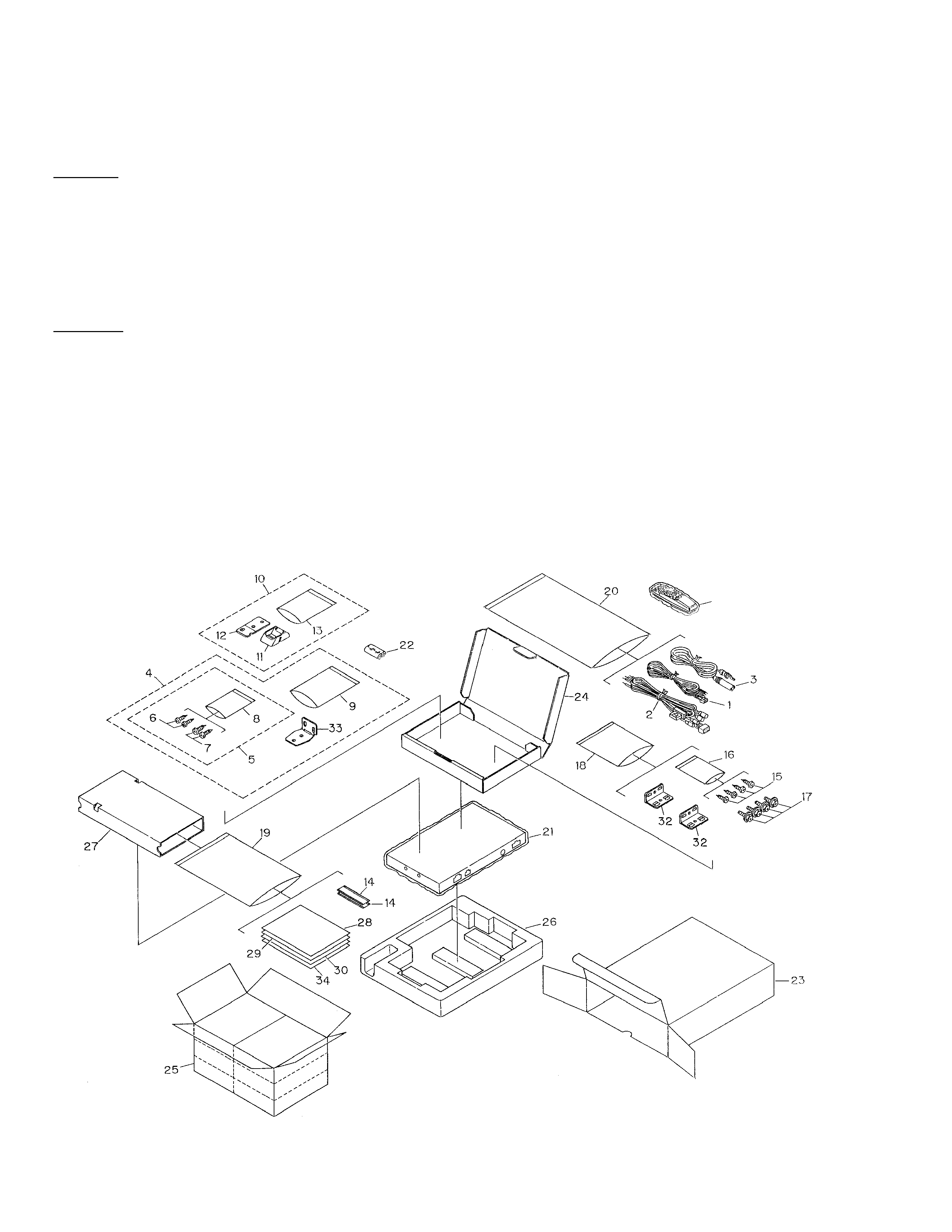
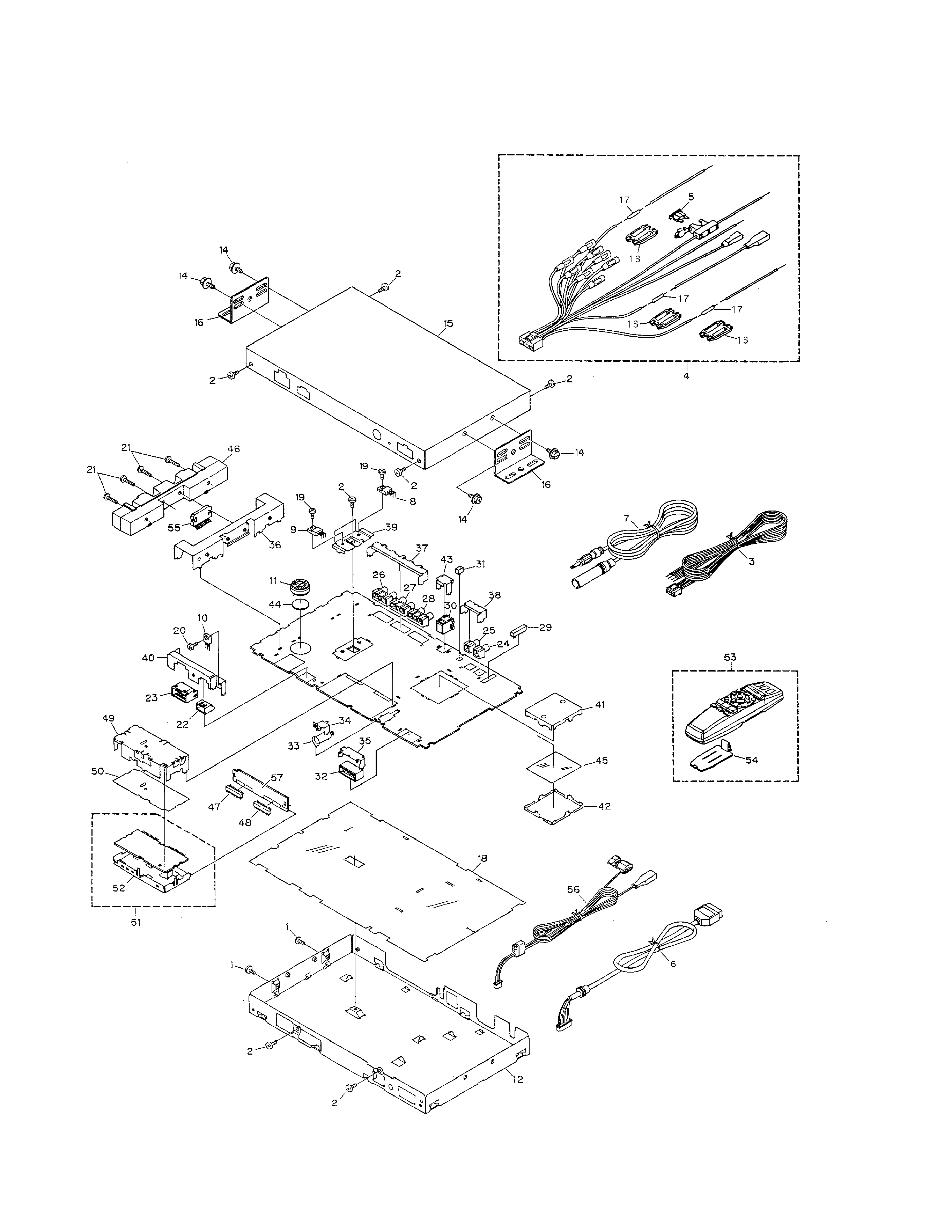
2. EXPLODED VIEWS AND PARTS LIST .......................2
3. SCHEMATIC DIAGRAM .............................................6
4. PCB CONNECTION DIAGRAM ................................14
5. ELECTRICAL PARTS LIST ........................................20
6. ADJUSTMENT..........................................................29
7. GENERAL INFORMATION .......................................31
7.1 IC ........................................................................31
7.2 BLOCK DIAGRAM ..............................................36
8. OPERATIONS AND SPECIFICATIONS.....................38
K-FED. JUNE 1998 Printed in Japan