PIONEER ELECTRONIC CORPORATION
4-1, Meguro 1-Chome, Meguro-ku, Tokyo 153-8654, Japan
PIONEER ELECTRONICS SERVICE INC.
P.O.Box 1760, Long Beach, CA 90801-1760 U.S.A.
PIONEER ELECTRONIC [EUROPE] N.V.
Haven 1087 Keetberglaan 1, 9120 Melsele, Belgium
PIONEER ELECTRONICS ASIACENTRE PTE.LTD. 253 Alexandra Road, #04-01, Singapore 159936
C PIONEER ELECTRONIC CORPORATION 1999
K-FZA. JAN. 1999 Printed in Japan
ORDER NO.
CRT2234
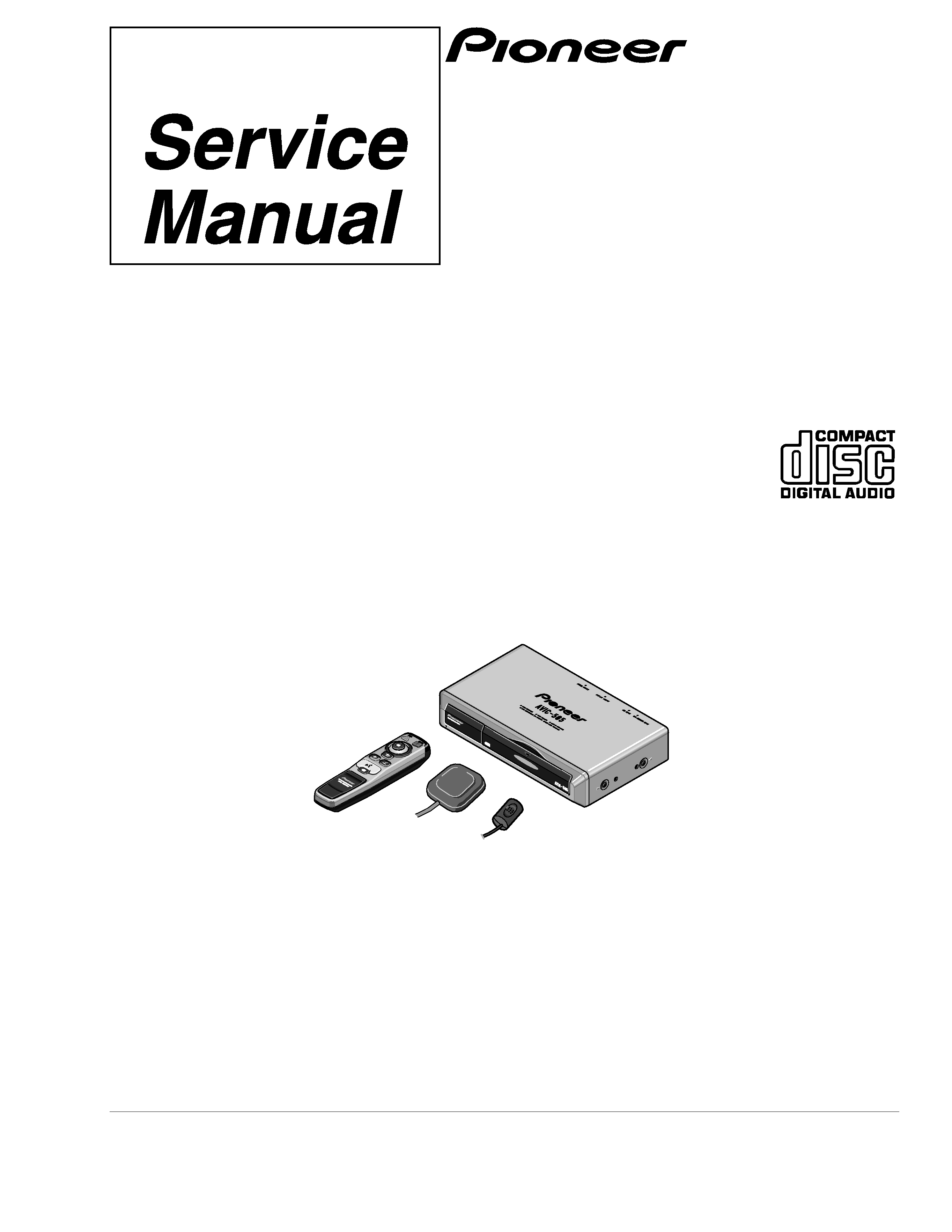
MOBILE NAVIGATION SYSTEM
AVIC-505
US,EW
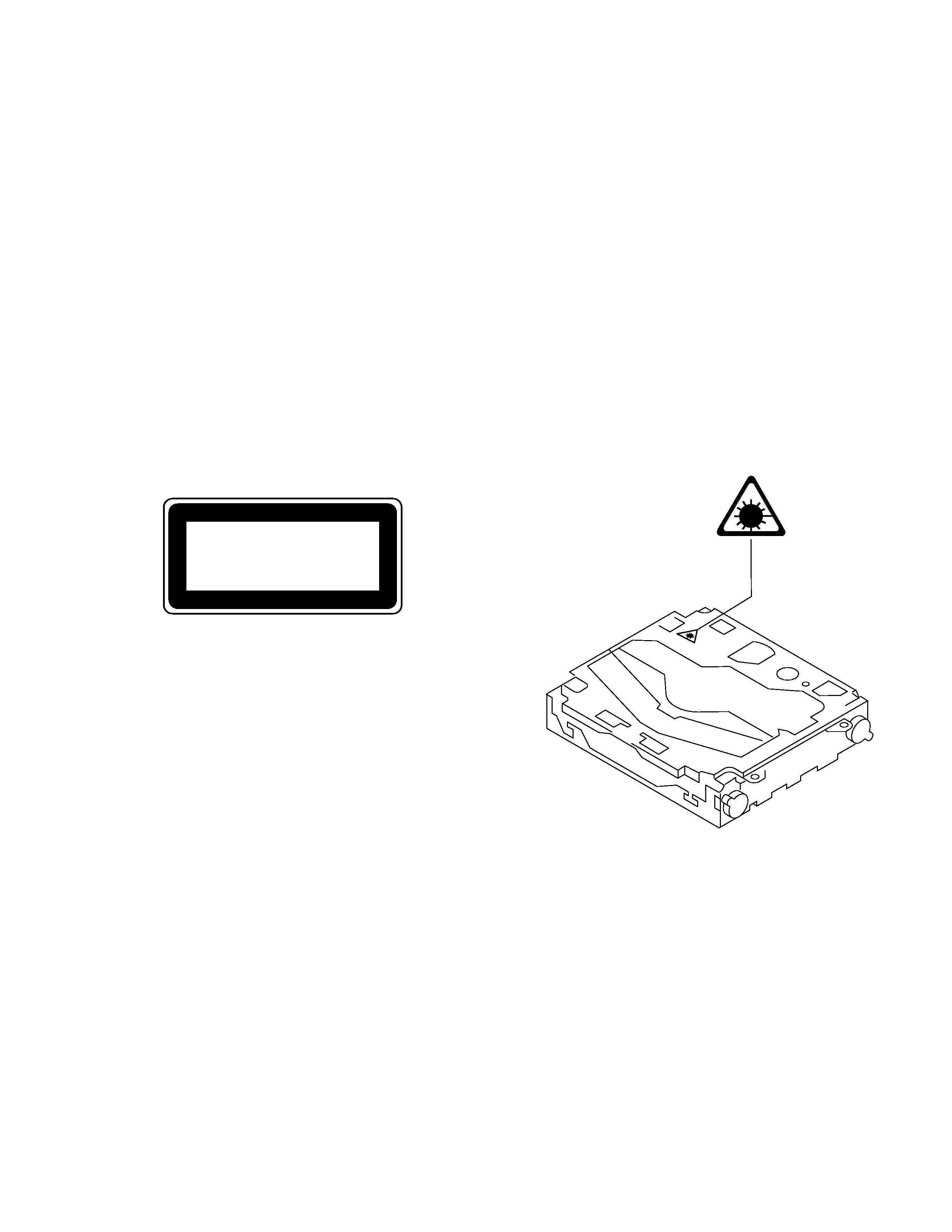
- See the separate manual CX-597(CRT1829) for the CD mechanism description, disassembly and circuit
description.
- The CD mechanism employed in this model is one of S7 series.
CONTENTS
1. SAFETY INFORMATION ............................................2
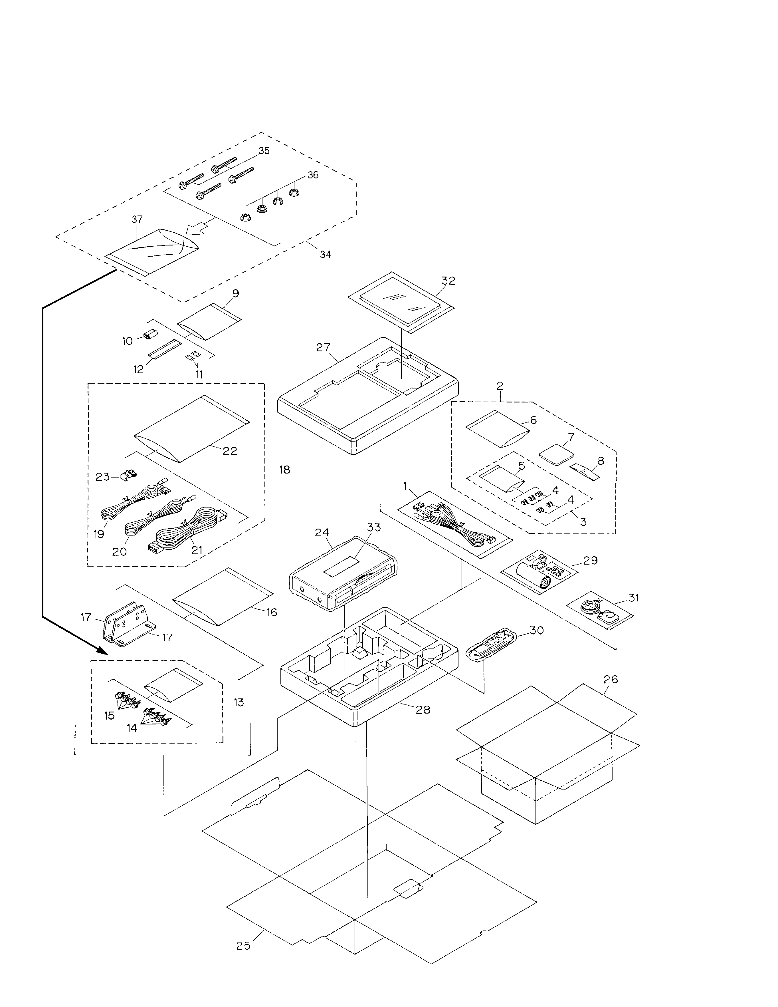
2. EXPLODED VIEWS AND PARTS LIST.......................4
3. SCHEMATIC DIAGRAM ...........................................12
4. PCB CONNECTION DIAGRAM ................................42
5. ELECTRICAL PARTS LIST ........................................52
6. ADJUSTMENT..........................................................61
7. GENERAL INFORMATION .......................................66
7.1 IC ........................................................................66
7.2 DIAGNOSIS ........................................................86
7.2.1 DISASSEMBLY..........................................86
7.2.2 TEST MODE...............................................88
7.2.3 TEST MODE (MAIN UNIT)........................90
7.2.4 HOW TO USE THE TEST DISC.................92
7.3 EXPLANATION ...................................................95
7.3.1 CIRCUIT DESCRIPTIONS ..........................95
7.3.2 BLOCK DIAGRAM .....................................96
8. OPERATIONS AND SPECIFICATIONS ....................98