
AVH-P5950DVD/XN/RC
5
5
678
56
7
8
C
D
F
A
B
E
CONTENTS
SAFETY INFORMATION .....................................................................................................................................2
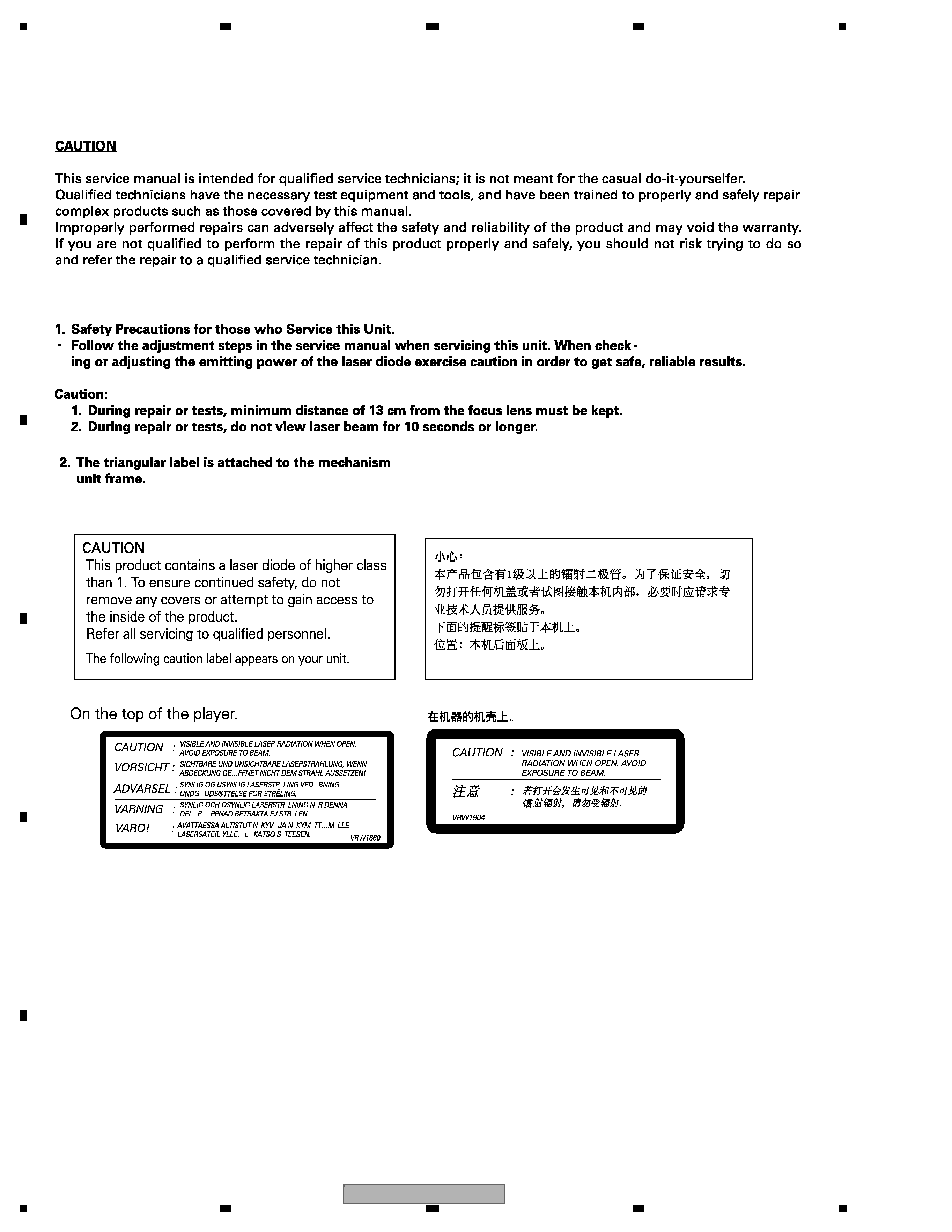
1. SERVICE PRECAUTIONS................................................................................................................................6
2. SPECIFICATIONS.............................................................................................................................................8
2.1 SPECIFICATIONS ......................................................................................................................................8
2.2 DISC/CONTENT FORMAT.........................................................................................................................9
2.3 PANEL FACILITIES ..................................................................................................................................10
2.4 CONNECTION DIAGRAM........................................................................................................................15
3. BASIC ITEMS FOR SERVICE ........................................................................................................................16
3.1 CHECK POINTS AFTER SERVICING .....................................................................................................16
3.2 PCB LOCATIONS.....................................................................................................................................17
3.3 JIG CONNECTION DIAGRAM .................................................................................................................18
4. BLOCK DIAGRAM ..........................................................................................................................................20
5. DIAGNOSIS ....................................................................................................................................................32
5.1 OPERATIONAL FLOW CHART................................................................................................................32
5.2 CONNECTOR FUNCTION DESCRIPTION .............................................................................................33
5.3 BACK END SECTION FLOW ...................................................................................................................34
6. SERVICE MODE.............................................................................................................................................56
6.1 DVD TEST MODE ....................................................................................................................................56
7. DISASSEMBLY ...............................................................................................................................................60
8. EACH SETTING AND ADJUSTMENT ............................................................................................................67
8.1 DVD ADJUSTMENT .................................................................................................................................67
8.2 VIDEO LEVEL ADJUSTMENT .................................................................................................................72
8.3 MOTHER UNIT ADJUSTMENT................................................................................................................74
8.4 INVERTER ADJUSTMENT ......................................................................................................................76
8.5 MONITOR ADJUSTMENT........................................................................................................................78
8.6 MONITOR TEST MODE...........................................................................................................................84
8.7 CALIBRATION TEST................................................................................................................................90
9. EXPLODED VIEWS AND PARTS LIST ..........................................................................................................98
9.1 PACKING..................................................................................................................................................98
9.2 EXTERIOR(1) .........................................................................................................................................100
9.3 EXTERIOR(2) .........................................................................................................................................102
9.4 EXTERIOR(3) .........................................................................................................................................106
9.5 EXTERIOR(4) .........................................................................................................................................108
9.6 DVD MECHANISM MODULE................................................................................................................. 110
10. SCHEMATIC DIAGRAM.............................................................................................................................. 112
10.1 MOTHER UNIT(SYSTEM PART)(GUIDE PAGE)................................................................................. 112
10.2 MOTHER UNIT(POWER SUPPLY PART)(GUIDE PAGE) ................................................................... 118
10.3 KEYBOARD UNIT ................................................................................................................................124
10.4 MONITOR PCB(MONITOR PART)(GUIDE PAGE) ..............................................................................126
10.5 MONITOR PCB(OSD & µCON PART)(GUIDE PAGE) .........................................................................132
10.6 DVD CORE UNIT(1/2)(GUIDE PAGE) .................................................................................................138
10.7 DVD CORE UNIT(2/2) ..........................................................................................................................144
10.8 COMPOUND UNIT(A) AND COMPOUND UNIT(B) .............................................................................146
10.9 RCA PCB..............................................................................................................................................147
10.10 UPPER PCB .......................................................................................................................................148
10.11 OPT PCB ............................................................................................................................................149
10.12 MAIN PCB UNIT(SERVICE), SWITCH PCB UNIT AND VOLUME PCB UNIT ..................................150
10.13 WAVEFORMS.....................................................................................................................................152
11. PCB CONNECTION DIAGRAM ..................................................................................................................154
11.1 MOTHER UNIT .....................................................................................................................................154
11.2 KEYBOARD UNIT.................................................................................................................................158
11.3 MONITOR PCB.....................................................................................................................................160
11.4 DVD CORE UNIT..................................................................................................................................164
11.5 COMPOUND UNIT(A) AND COMPOUND UNIT(B) .............................................................................168
11.6 RCA PCB ..............................................................................................................................................169
11.7 UPPER PCB .........................................................................................................................................170
11.8 OPT PCB ..............................................................................................................................................171
11.9 MAIN PCB UNITSERVICE), SWITCH PCB UNIT AND VOLUME PCB UNIT......................................172
12. ELECTRICAL PARTS LIST.........................................................................................................................173


/KC Owner's Manual")


