PIONEER CORPORATION
4-1, Meguro 1-Chome, Meguro-ku, Tokyo 153-8654, Japan
PIONEER ELECTRONICS SERVICE INC.
P.O.Box 1760, Long Beach, CA 90801-1760 U.S.A.
PIONEER EUROPE NV
Haven 1087 Keetberglaan 1, 9120 Melsele, Belgium
PIONEER ELECTRONICS ASIACENTRE PTE.LTD. 253 Alexandra Road, #04-01, Singapore 159936
C PIONEER CORPORATION 2000
K-ZZD. MAY 2000 Printed in Japan
ORDER NO.
CRT2510
COLOR LCD REAR DISPLAY
AVD-W8000
UC,EW
Service
Manual
AVD-W8000/UC
CONTENTS
1. SAFETY INFORMATION ............................................2
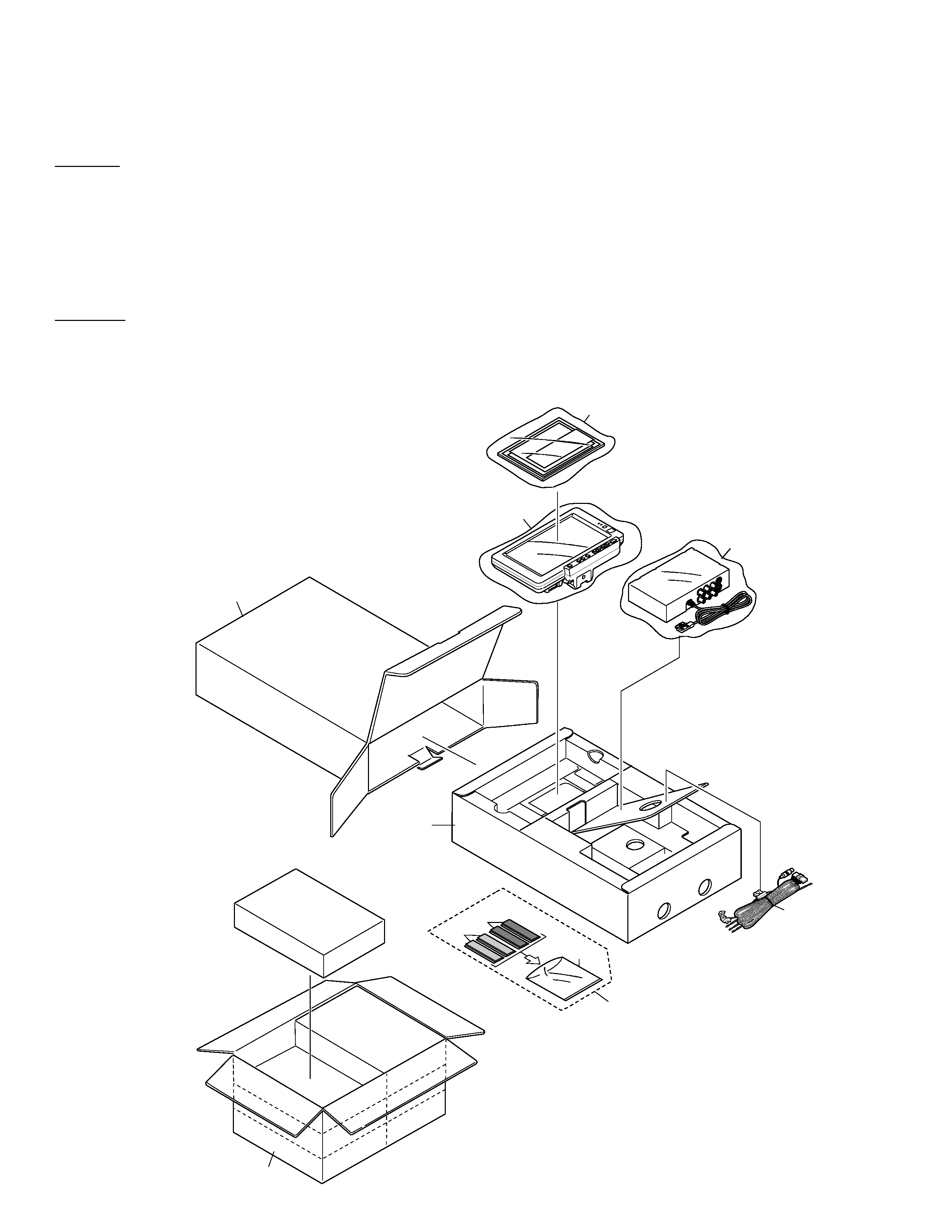
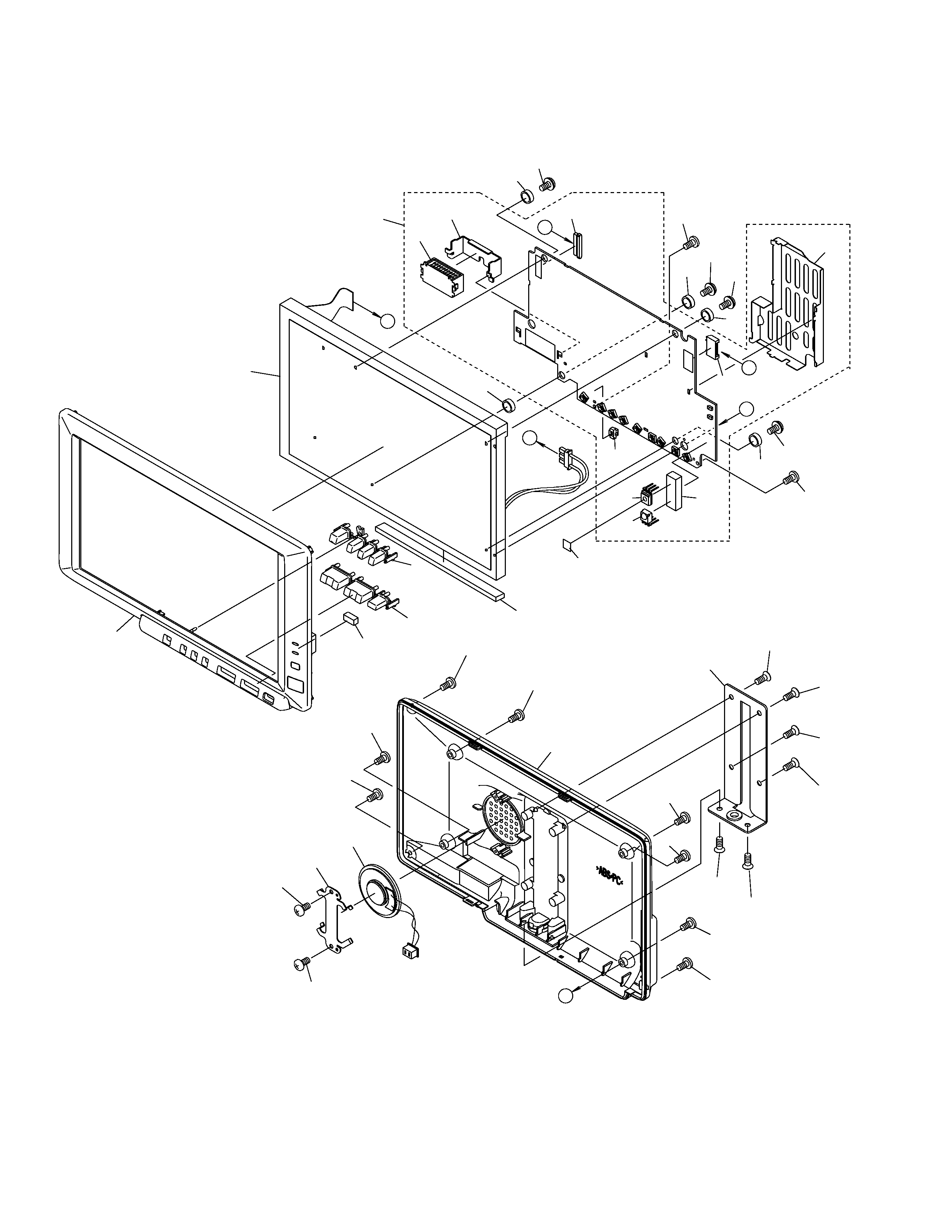
2. EXPLODED VIEWS AND PARTS LIST.......................2
3. BLOCK DIAGRAM AND SCHEMATIC DIAGRAM.....8
4. PCB CONNECTION DIAGRAM ................................32
5. ELECTRICAL PARTS LIST ........................................41
6. ADJUSTMENT..........................................................50
7. GENERAL INFORMATION .......................................58
7.1 DIAGNOSIS ........................................................58
7.1.1 TEST MODE ..............................................58
7.1.2 DISASSEMBLY .........................................60
7.2 IC ........................................................................61
7.3 EXPLANATION ...................................................72
7.3.1 CIRCUIT DIAGRAM ..................................72
7.3.2 OPERATIONAL FLOW CHART.................74
8. OPERATIONS AND SPECIFICATIONS ....................76
- High voltage is generated in the inverter when the power is supplied to the system. To avoid an electric shock,
reconfirm that the power switch is set to OFF before starting operation.
- In case of repair, exchange either Decoder IC (IC301 : CXA2019AQ) of Power Supply Assy or EEPROM(IC603 : S-
29131AFJ). When you adjust the visual signals, make sure to use Monitor Assy.
CH-CALL/
C
LOW-
REFRECTI