COLOR DISPLAY
· AVD-505/US
COLOR DISPLAY
AVD-505
US,EW
Service
Manual
PIONEER ELECTRONIC CORPORATION
4-1, Meguro 1-Chome, Meguro-ku, Tokyo 153-8654, Japan
PIONEER ELECTRONICS SERVICE INC.
P.O.Box 1760, Long Beach, CA 90801-1760 U.S.A.
PIONEER ELECTRONIC [EUROPE] N.V.
Haven 1087 Keetberglaan 1, 9120 Melsele, Belgium
PIONEER ELECTRONICS ASIACENTRE PTE.LTD. 501 Orchard Road, #10-00, Wheelock Place, Singapore 23880
C PIONEER ELECTRONIC CORPORATION 1998
ORDER NO.
CRT2239
CONTENTS
1. SAFETY INFORMATION ............................................2
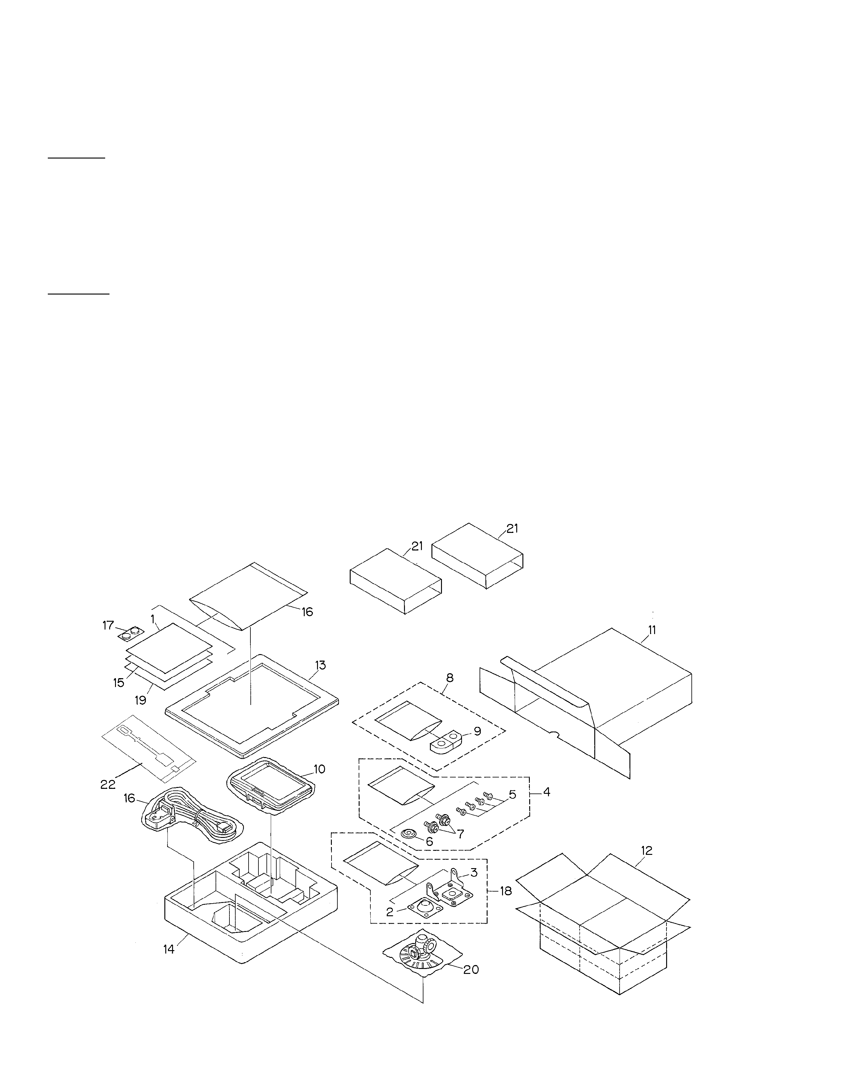
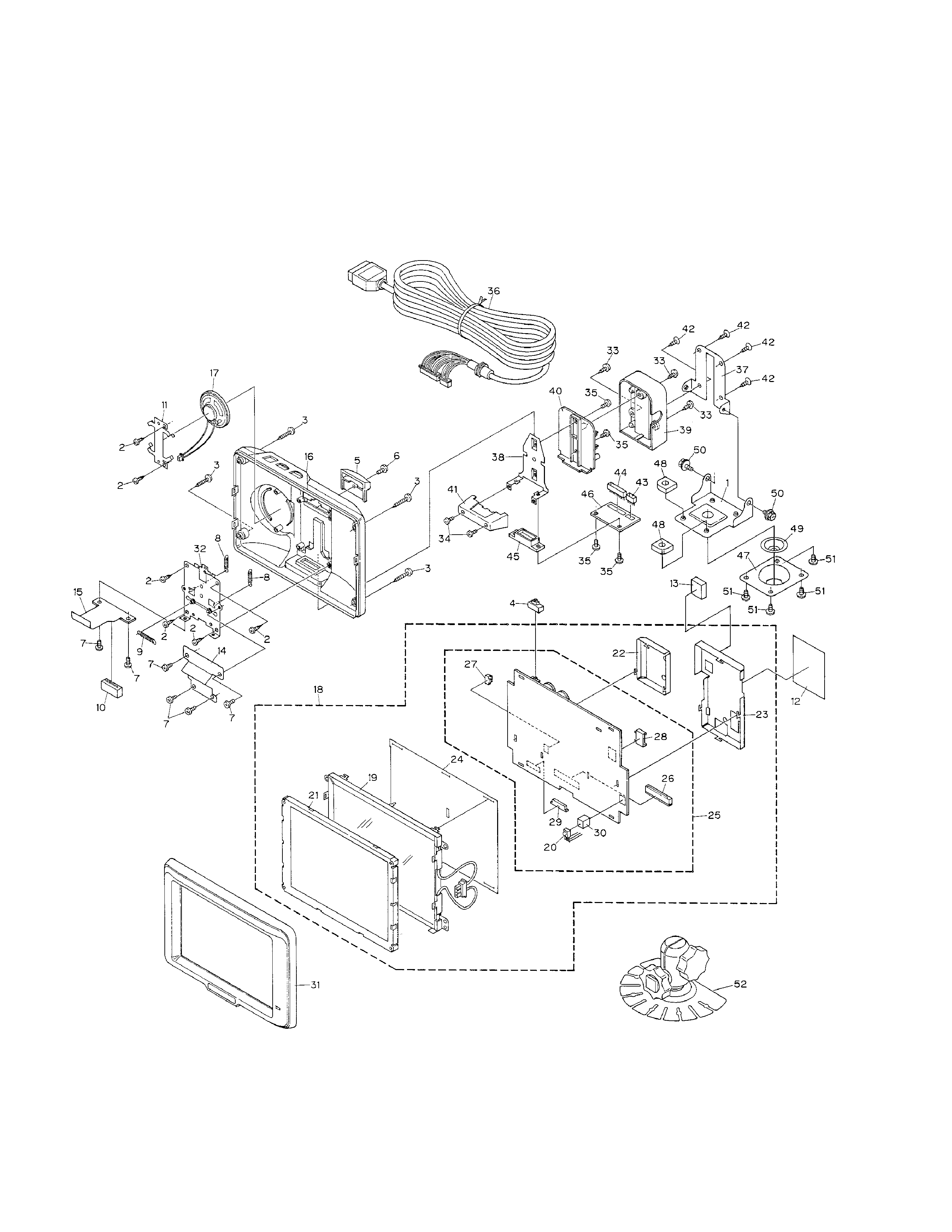
2. EXPLODED VIEWS AND PARTS LIST .......................2
3. SCHEMATIC DIAGRAM .............................................6
4. PCB CONNECTION DIAGRAM ................................14
5. ELECTRICAL PARTS LIST ........................................19
6. ADJUSTMENT..........................................................23
7. GENERAL INFORMATION .......................................25
7.1 IC ........................................................................25
7.2 DISASSEMBLY ...................................................28
7.3 BLOCK DIAGRAM ..............................................29
8. OPERATIONS AND SPECIFICATIONS.....................30
K-ZZD. JULY 1998 Printed in Japan
- Precautions on Safety for Replacement of Backlight
· High voltage is generated in the inverter when the power is supplied to the system. To avoid an electric
shock, reconfirm that the power switch is set to OFF before starting operation.
· The fluorescent tube and high-voltage parts have high temperature immediately after the power
switch of the main unit is set to OFF. To avoid burning your hand or similar accidents, wait awhile after
turning the power to OFF, then start operation.
· High voltage may be charged to the inverter immediately after the power switch of the main unit is set
to OFF. Wait awhile after turning the power to OFF, then start operation.
· In some cases, the fluorescent tube of backlight may be damaged. Take adequate caution for injury
during operation.