PIONEER A-A6-S Service Manual

Cover page of PIONEER A-A6-S Service Manual

Service Manual for PIONEER A-A6-S, downloadable as a PDF file.

Manual details

  • Immediate download after payment.
  • Delivered as a PDF file.
  • The manual has 4 pages
  • File size: 0.26 MB
  • Available language versions: English
  • Different language versions may vary sligthly in file size and page count.

We guarantee that...

  • our manuals are complete,
  • the manual includes circuit diagrams,
  • our manuals are checked with antivirus,
  • We'll issue refund if the manual is damaged, incomplete or unreadable (our refund policy)

Sample pages

Thumbnail of page 1Thumbnail of page 2Thumbnail of page 3Thumbnail of page 4
Thumbnail of page 5Thumbnail of page 6Thumbnail of page 7Thumbnail of page 8
background image
ORDER NO.
PIONEER CORPORATION 4-1, Meguro 1-chome, Meguro-ku, Tokyo 153-8654, Japan
PIONEER ELECTRONICS (USA) INC. P.O. Box 1760, Long Beach, CA 90801-1760, U.S.A.
PIONEER EUROPE NV Haven 1087, Keetberglaan 1, 9120 Melsele, Belgium
PIONEER ELECTRONICS ASIACENTRE PTE. LTD. 253 Alexandra Road, #04-01, Singapore 159936
PIONEER CORPORATION 2007
RRV3639
INTEGRATED AMPLIFIER
A-A6-S
THIS MANUAL IS APPLICABLE TO THE FOLLOWING MODEL(S) AND TYPE(S).
This service manual should be used together with the following manual(s):
Model
Type
Power Requirement
Remarks
A-A6-S
WAXCN5
AC 220 V
Model
Order No.
Remarks
A-A9-J/MYXCN5
RRV3515
T-ZZV AUG. 2007 Printed in Japan
background image
A-A6-S
2
12
34
1
234
C
D
F
A
B
E
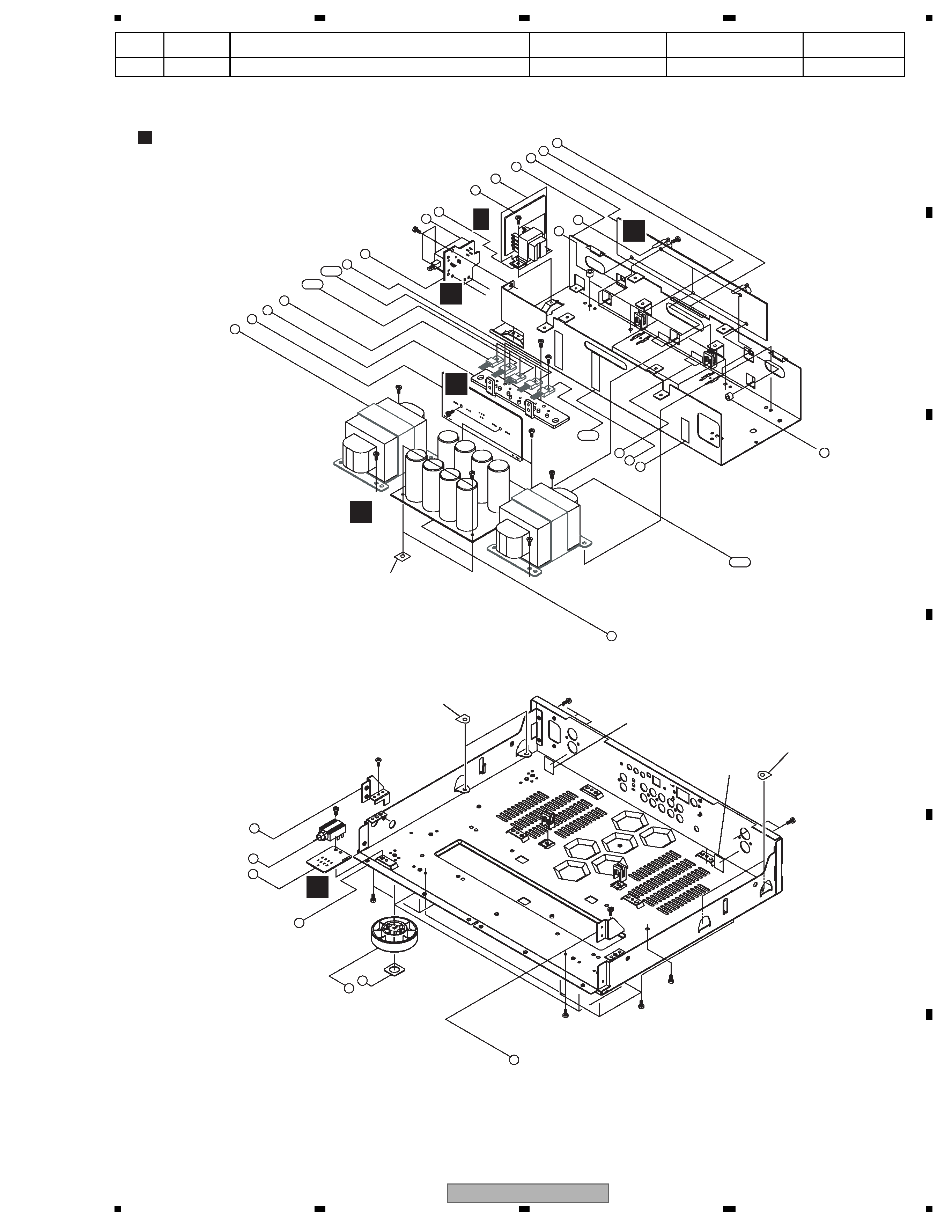
1. CONTRAST OF MISCELLANEOUS PARTS
1.1 CONTRAST TABLE
A-A6-J/MYXCN5 and A-A6-S/WAXCN5 are constructed the same except for the following:
Parts marked by "NSP" are generally unavailable because they are not in our Master Spare Parts List.
The
mark found on some component parts indicates the importance of the safety factor of the part.
Therefore, when replacing, be sure to use parts of identical designation.
Screws adjacent to
mark on product are used for disassembly.
For the applying amount of lubricants or glue, follow the instructions in this manual.
(In the case of no amount instructions, apply as you think it appropriate.)
Nos. indicate the pages and Nos. in the service manual for the base model.
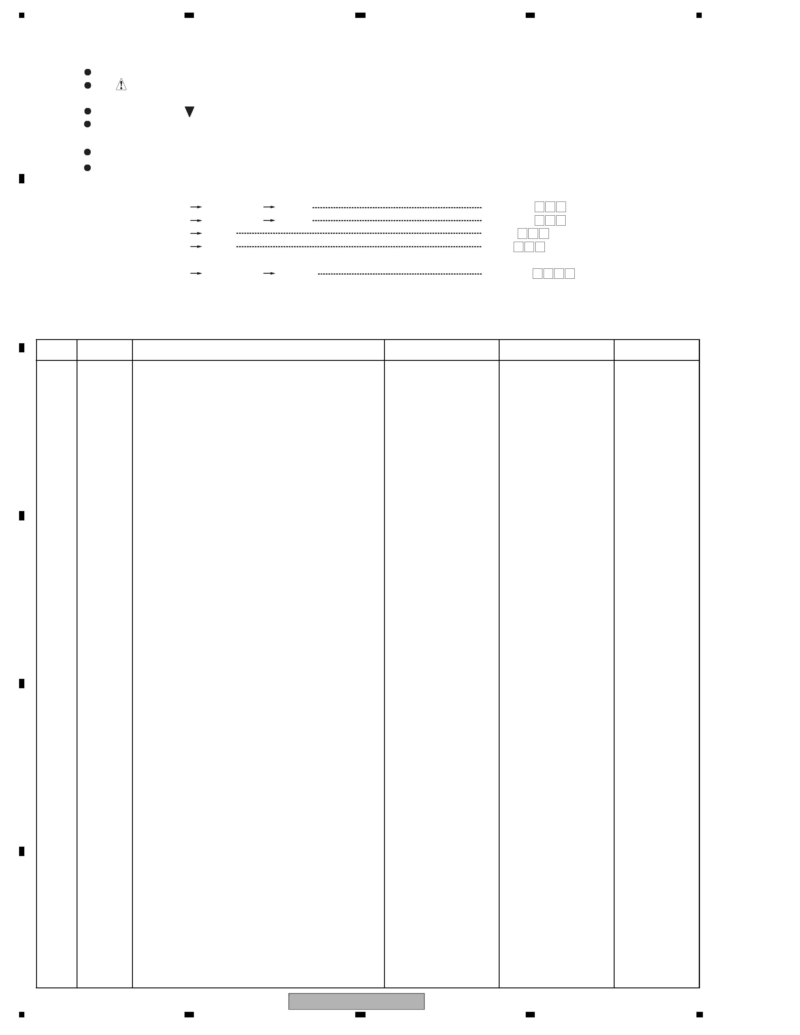
NOTES:
When ordering resistors, first convert resistance values into code form as shown in the following examples.
Ex.1 When there are 2 effective digits (any digit apart from 0), such as 560 ohm and 47k ohm (tolerance is shown by J=5%,
and K=10%).
Ex.2 When there are 3 effective digits (such as in high precision metal film resistors).
561
473
R50
1R0
5621
560
47k
0.5
1
RD1/4PU
J
RD1/4PU
J
RN2H
K
RS1P
K
56
x 10 1
47
x 10 3
R50
1R0
561
473
5.62k
RN1/4PC
F
562
x 10 1
5621
Mark
No.
Symbol and Description
A-A6-J/MYXCN5
A-A6-S/WAXCN5
Remarks
PCB ASSEMBLIES
NSP
1..PCB TOTAL ASSY
7025HA0603010-IL
7025HA0603050-IL
2..SUB TRANS ASSY
702806535A010-IL
702806535A050-IL
NSP
1..PCB TOTAL ASSY
7025HA0603011-IL
7025HA0603051-IL
Constructed same.
PACKING SECTION
>
P11-1
Power Cable
L068250160020-IL
L068250100050-IL
P11-2
Remote Control
8300747200010-IL
8300747400010-IL
P11-5
Operating Instructions
5707000000120-IL
Not used
(English/French/German/Dutch/Italian/Spanish)
P11-5
Operating Instructions (Chinese)
Not used
5707000000670-IL
P11-8
Box, Gift
6007210930010-IL
6007210930060-IL
NSP
P11-9
Warranty Card
ARY7065
ARY7046
P11-10
Battery Cover
AZN8024
AZN8025
P11-11
Label (WEEE)
ARW7322
Not used
Polyethylene Bag
Not used
6330210302000-IL
EXTERIOR SECTION
>
P14-1
Trans Main L
8200660550340-IL
8200660550380-IL
>
P14- 1-1
Trans Main R
8200660550390-IL
8200660550430-IL
P14-14
Cabinet Top Cover
3007210796000-IL
3007210796010-IL
P14-15
Knob Volume
5088211388000-IL
5088211388100-IL
P14-16
Knob Input
5088211368000-IL
5088211368100-IL
P14-18
Panel Front L
3067212788000-IL
ANB7446
P14-21
Lens Remocon
3710210683000-IL
3710210683100-IL
P14-23
Panel Front R
3067212808000-IL
ANB7447
P14-24
Frame Panel
3217211311000-IL
3217211311100-IL
P14-25
Knob Power
5087211391000-IL
5087211391010-IL
NSP
P14-32
Chassis Main & Back
3207212016000-IL
3207212016040-IL
P14-52
Foot
4000210391000-IL
4007210391000-IL
P14-S4
Screw
1500040103P41-IL
1500040104P41-IL
NSP
Cap
4507210218000-IL
Not used
NSP
Cap
4507210238000-IL
Not used
Sheet
5227000000240-IL
Not used
Sheet
Not used
1210210502000-IL
No.1
Sheet
Not used
1210210512000-IL
No.2
background image
A-A6-S
3
56
7
8
56
7
8
C
D
F
A
B
E
Notes : The number in the Remarks column correspond to the numbers on "EXPLODED VIEWS".
For PCB assemblies, Refer to "1.2 CONTRAST OF PCB ASSEMBLIES".
Sheet
Not used
1210210522000-IL
No.3
Mark
No.
Symbol and Description
A-A6-J/MYXCN5
A-A6-S/WAXCN5
Remarks
33
34
35
52
53
32
S13*3
S10
S3*4
S3*4
S9
S9
64
S9*2
S9
72
6
1
5
7
31
S11*5
S9
S2*2
S9
S9
S9
S10*3
S9*2
S10*2
S9*2
S11*2
8
10
11
9
S10*5
70
73
74
76
72
77
2
3
4
75
4
4-1
4-2
4-3
1-1
No.1
No.2
No.3
No.3
No.2
EXPLODED VIEWS
L F
E
M
N
K
O
background image
A-A6-S
4
12
34
1
234
C
D
F
A
B
E
1.2 CONTRAST OF PCB ASSEMBLIES
LF SUBTRANSASSY
702806535A010-IL and 702806535A050-IL are constructed the same except for the following:
Mark
Symbol and Description
702806535A010-IL
702806535A050-IL
>
T801
8200280150330-IL
8200280150370-IL
CN804
L000351040100-IL
Not used
CN810 (same position as CN804)
Not used
L000351040100-IL

Reviews

There are no reviews of this manual yet.