PIONEER A-209/SDFXJ Owner's Manual

Cover page of PIONEER A-209/SDFXJ Owner's Manual

Owner's Manual for PIONEER A-209/SDFXJ, downloadable as a PDF file.

We also have service manual to this model.

Manual details

  • Immediate download after payment.
  • Delivered as a PDF file.
  • The manual has 32 pages
  • File size: 1.56 MB
  • Available language versions: Japanese, English, Spanish
  • Different language versions may vary sligthly in file size and page count.

We guarantee that...

  • our manuals are complete,
  • our manuals are checked with antivirus,
  • We'll issue refund if the manual is damaged, incomplete or unreadable (our refund policy)

Sample pages

Thumbnail of page 1Thumbnail of page 2Thumbnail of page 3Thumbnail of page 4
Thumbnail of page 5Thumbnail of page 6Thumbnail of page 7Thumbnail of page 8
Thumbnail of page 9
background image
A-209
A-109
Operating Instructions
Manual de instrucciones
STEREO AMPLIFIER
AMPLIFICADOR ESTEREOFONICO
background image
A-209
A-109
Operating Instructions
Manual de instrucciones
STEREO AMPLIFIER
AMPLIFICADOR ESTEREOFONICO
background image
2
220V
110V
120-127V
240V
Mains voltages in Saudi Arabia are 127 V and
220 V only. Never use this model with the 110
V setting in Saudi Arabia.
H019 En
LINE VOLTAGE SELECTOR SWITCH H038 En
The line voltage selector switch is located on the rear panel.
Check that it is set properly before plugging the power cord
into the outlet. If the voltage is not properly set or if you move
to an area where the voltage requirements differ, adjust the
selector switch as follows:
¶ Be sure to disconnect the power cord from its outlet before
making this adjustment.
¶ Use a medium-sized (flat blade) screwdriver. Insert the tip
of the screwdriver into the groove of the selector switch
and turn it so that the power voltage marking of your area
points to the arrow.
CAUTION 220 V
Power source voltage is factory adjusted 220 volts. If your area
is different, change voltage selectors settings.
H038 En
Operating Environment H045 En
Operating environment temperature and humidity:
+5°C ­ +35°C (+41°F ­ +95°F); less than 85%RH (cooling vents
not blocked)
Do not install in the following locations
÷ Location exposed to direct sunlight or strong artificial light
÷ Location exposed to high humidity, or poorly ventilated
location
background image
3
English
CONTENTS
FEATURES
7 Low power consumption design.
7 High-power Output:
A-209 ..................................... 60W+60W/4
(DIN)
45W+45W/8
(DIN)
A-109 ..................................... 40W+40W/8
(DIN)
7 Wide-Range Linear Circuit
This new current feedback circuit assures improved oper-
ating stability for flat output impedance and stable driving
of speakers across the full range of frequencies.
7 Complementary capacitor pair.
7 Advanced Direct Energy MOS Power Amp
Pioneer incorporates highest quality amp circuitry featur-
ing Advanced Direct Energy MOS FET devices which can
achieve higher performance. Together with Pioneer's origi-
nal Wide Range Linear Circuit technology they reduce
power consumption while maintaining the power output of
current models.
In terms of performance, this technology contributes to flat
damping factor characteristics across the audio spectrum.
It also allows a wide range and especially ultra high fre-
quencies to be reproduced more accurately and improves
power linearity.
7 Stabilizer
Transformer stabilizer and stabilizer frame (attached to
chassis) deliver powerful sound.
INSTALLATION
LOCATION
Install the unit in a well-ventilated location where it
will not be exposed to high temperatures or humid-
ity.
Do not install the unit in a location which is exposed to direct
rays of the sun, or near hot appliances or radiators. Excessive
heat can adversely affect the cabinet and internal compo-
nents. Installation of the unit in a damp or dusty environment
may also result in a malfunction or an accident.
(Avoid
installation near cookers etc., where the unit may be exposed
to oily smoke, steam or heat.)
Do not install the unit on a tottered stand, nor on an unstable
or inclined surface.
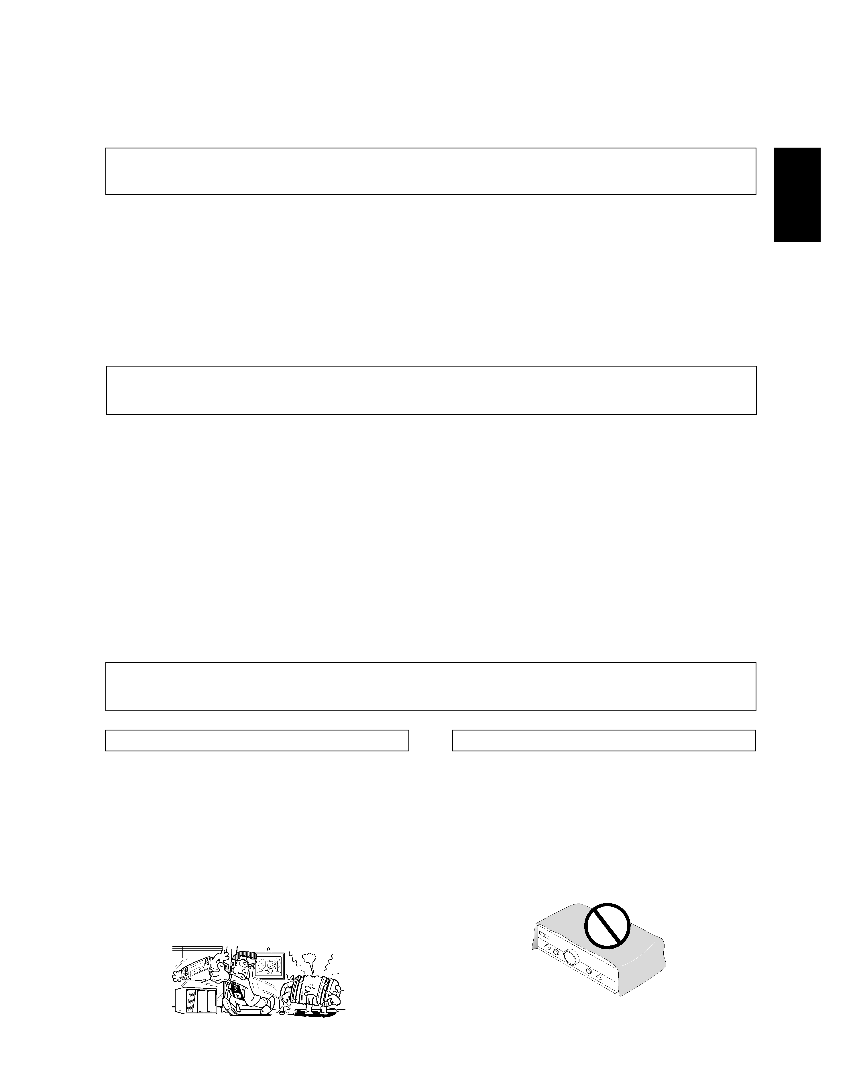
VENTILATION
When installing this unit, make sure to leave space around the
unit for ventilation to improve heat radiation (at least 60 cm at
top, 10 cm at rear, and 30 cm at each side).
WARNING: Slot and openings in the cabinet are provided for
ventilation and to ensure reliable operation of the product and
to protect it from overheating, to prevent fire hazard, the
openings should never be blocked and covered with items,
such as newspapers, table-cloths, curtains, etc. Also do not
put the apparatus on the thick carpet, bed, sofa, or fabric
having a thick pile.
FEATURES ......................................................................... 3
INSTALLATION .................................................................. 3
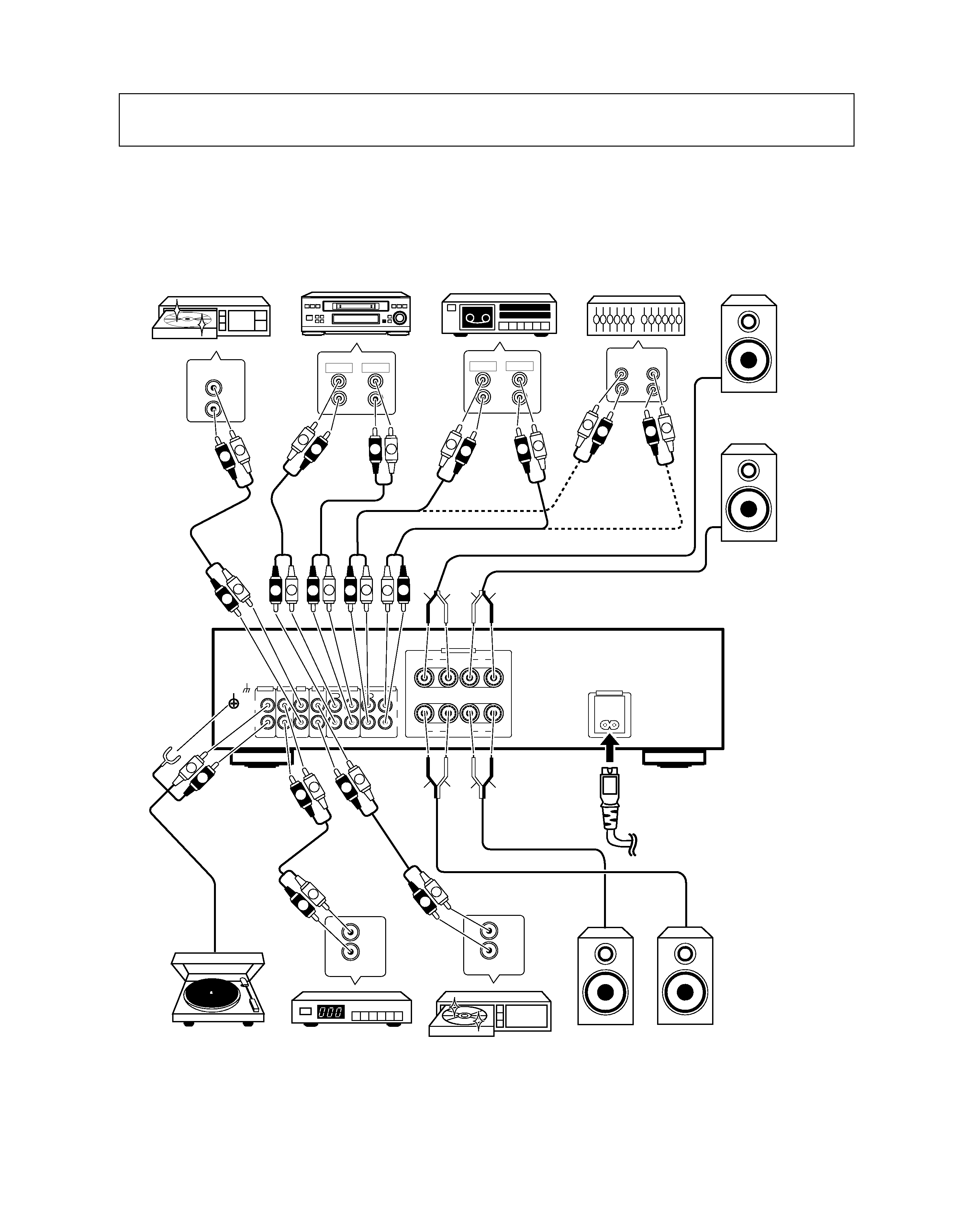
CONNECTIONS .................................................................. 4
PANEL FACILITIES ............................................................. 6
OPERATIONS ..................................................................... 9
TROUBLESHOOTING ...................................................... 11
SPECIFICATIONS ............................................................. 12
Thank you for buying this PIONEER product.
Please read through these operating instructions so you will know how to operate your model properly. After you have finished
reading the instructions, put them away in a safe place for future reference.
background image
4
CONNECTIONS
Cassette deck/CD recorder/
MD recorder
Cassette deck
Adaptor component
(graphic equalizer etc.)
CD player
Speaker system B
(A-209 only)
Right (R)
Left (L)
SPEAKERS
RL
R
A
B
L
SIGNAL
GND
L
R
PHONO
IN
TUNER
IN
CD
IN
LINE
IN
TAPE 1/CD-R/MD
REC
PLAY
REC
PLAY
TAPE 2 MONITOR
OUT
IN
OUT
IN
L
R
AC INLET
REC
PLAY
L
R
REC
PLAY
L
R
CD
OUT
L
R
IN
OUT
L
R
FM-AM
OUT
L
R
L
R
L
R
ª
·
ª
·
L
L
R
R
L
R
L
R
L
R
L
R
ª
·
ª
AUDIO OUT
L
R
L
R
L
R
L
R
MINIDISC
R
L
R
L
R
L
·
L
R
L
L
R
R
ª
·
ª
·
DVD
The illustration shows the A-209.
To an AC wall socket.
Left (L)
Right (R)
DVD player, VCR, etc.
Tuner
Turntable
Speaker system A
Before making or changing the connections, switch off the power and disconnect the power cord from the AC
outlet.
H029BEn
See page 5.
background image
5
English
CONNECTIONS
\
NOTE:
Do not allow any of the cord conductors to protrude from the
terminals or touch any other conductors. Malfunctioning or
breakdowns may occur when conductors come into contact
with each other.
Speaker Impedance
[A-209]
When speaker systems are connected to only SPEAKERS A
or SPEAKERS B terminals, such speakers should have rated
impedance in the range of 4­16
.
When speaker are connected to both A and B terminals, they
should have a rated impedance in the range of 8 ­32
.
[A-109]
The speaker systems used should have a rated impedance in
the range of 6 - 16
.
CONNECTING THE SPEAKER CORDS
2. Loosen the knob and insert the wire core into the
terminal hole.
3. Tighten the knob to fix the wire core in place.
10mm
1. Strip off the vinyl covering and twist the tip of the
wire core.
CONNECTING THE INPUT/OUTPUT
CORDS
Connect the white plug to the L (left) channel, and the red plug
to the R (right) channel. Be sure to push the plugs securely.
L
R
Left channel
White plug
Right channel
Red plug
Twist the wire core
2
3
1
AC POWER CORD
Plug in the power cord first to the amplifier and then to the
wall outlet after you have finished hooking up the rest of your
equipment.
CAUTION!
· Do not use any other power cord than the one supplied
with this unit.
· The amplifier should be disconnected by removing the
mains plug from the wall socket when not in regular use,
e.g. when on vacation.
Please use the correct cord and plug for your region.
European two pin plug
with two pin flat-bladed
converter plug (for 200
volts or greater power
supply)
Taiwanese two pin flat-bladed
plug
For Taiwan exclusively
For regions with two pin flat-bladed plug and 200 volts or
greater power supply
Make sure the voltage selector
has been switched to the 110 V
position before plugging in the
AC power cord.

Reviews

There are no reviews of this manual yet.