ONKYO TX-SR800 Service Manual

Cover page of ONKYO TX-SR800 Service Manual

Service Manual for ONKYO TX-SR800, downloadable as a PDF file.

We also have owner's manual to this model.

Manual details

  • Immediate download after payment.
  • Delivered as a PDF file.
  • The manual has 88 pages
  • File size: 6.76 MB
  • Available language versions: English
  • Different language versions may vary sligthly in file size and page count.

We guarantee that...

  • our manuals are complete,
  • the manual includes circuit diagrams,
  • our manuals are checked with antivirus,
  • We'll issue refund if the manual is damaged, incomplete or unreadable (our refund policy)

Sample pages

Thumbnail of page 1Thumbnail of page 2Thumbnail of page 3Thumbnail of page 4
Thumbnail of page 5Thumbnail of page 6Thumbnail of page 7Thumbnail of page 8
Thumbnail of page 9
background image
TX-SR800
SERVICE MANUAL
SERVICE MANUAL
Black and Golden models
Ref. No. 3754
112002
STANDBY/ON
STANDBY
PHONES
MASTER VOLUME
TAPE
TUNER
PHONO
C D
VIDEO
4
VIDEO
5
VIDEO
3
VIDEO
2
VIDEO
1
DVD
OFF
ZONE
2
REC OUT
DISPLAY
DIMMER
AUDIO
SELECTOR
ZONE
2 ()
GRN
REC ()
RED
VCR
2
VCR
1
S VIDEO
AUDIO
VIDEO
L
R
DIGITAL
VIDEO
5 INPUT
OFF
ON
POWER
TX-SR800
PURE AUDIO
UPSAMPLING
CLEAR
DSP
A-FORM LISTENING MODE MEMORY
THX
SURROUND
DIRECT/PURE AUDIO
STEREO
FM MODE
MEMORY
ENTER
RETURN
SETUP
TUNING
PRESET
AV RECEIVER
MODEL
TX-SR800
BMDD,BMDC
120V AC, 60Hz
BMPA,GMPA
230~240V AC, 50Hz
BMWT,GMWT,GMWR
120/220~230V AC, 50/60Hz
GMGT
220V AC, 50Hz
SAFETY-RELATED COMPONENT
WARNING!!
COMPONENTS IDENTIFIED BY MARK
ON THE
SCHEMATIC DIAGRAM AND IN THE PARTS LIST ARE
CRITICAL FOR RISK OF FIRE AND ELECTRIC SHOCK.
REPLACE THESE COMPONENTS WITH ONKYO
PARTS WHOSE PART NUMBERS APPEAR AS SHOWN
IN THIS MANUAL.
MAKE LEAKAGE-CURRENT OR RESISTANCE
MEASUREMENTS TO DETERMINE THAT EXPOSED
PARTS ARE ACCEPTABLY INSULATED FROM THE
SUPPLY CIRCUIT BEFORE RETURNING THE
APPLIANCE TO THE CUSTOMER.
background image
TX-SR800
SPECIFICATIONS
AMPLIFIER SECTION
Continuous average power output (FTC)
All channels:
100 W per channel min. RMS at 8
Ohm, 2 channels driven from 20 Hz to
20 kHz with no more than 0.08%
total harmonic distortion.
130 W min. RMS at 6 Ohm, 2 channels
driven from 1 kHz with no more
than
0.1%
total
harmonic
distortion.
Continuous power output (DIN) 135 W at 6 Ohm
Maximum power output (EIAJ)
160 W at 6 Ohm
Dynamic power output (stereo)
2 x 250 W at 3Ohm
2 x 210 W at 4Ohm
2 x 130 W at 8Ohm
Total harmonic distortion:
0.08% at rated power
0.08% at 1 W output
IM distortion:
0.08% at rated power
0.08% at 1 W output
Damping factor:
60 at 8 Ohm
Input sensitivity and impedance
PHONO:
2.5 mV, 50 kohm
LINE (CD, TAPE, DVD,
VIDEO 1-5):
200 mV, 50 k ohm
MULTICHANNEL INPUT
(FRONT L/C/R, SURROUND
L/R, SURROUND BACK L/R): 200 mV, 50 k ohm
(SUBWOOFER):
36 mV, 50 k ohm
COAXIAL 1, 2, 3 (DIGITAL):
0.5 Vp-p, 75 Ohm
DVD, VIDEO 1, 2, 3, 4, 5:
1 Vp-p, 75 Ohm
1 Vp-p, 75 Ohm (Y)
0.28 Vp-p, 75 Ohm (C)
COMPONENT VIDEO 1, 2:
1 Vp-p, 75 Ohm (Y)
0.7 Vp-p, 75 Ohm (PB, PR )
Output level and impedance
Rec out (TAPE, VIDEO 1, 2):
200 mV, 470 Ohm
Pre out:
1 V, 470 Ohm
VIDEO (VIDEO 1, 2, MONITOR
OUT, ZONE 2 OUT):
1 Vp-p, 75Ohm
1 Vp-p, 75Ohm(Y)
0.28 p-p, 75Ohm (C)
COMPONENT VIDEO OUT:
1 Vp-p, 75Ohm(Y)
0.7 Vp-p, 75 Ohm (P
B
, P
R
)
Phono overload:
120 mV RMS at 1 kHz, 0.5% T.H.D.
Frequency response:
10 Hz to 100 kHz : +1/ ­3 dB
(CD in Direct mode)
RIAA deviation:
20 Hz to 20 kHz : ±0.8 dB
Tone Control
Bass:
±10 dB at 50 Hz
Treble:
±10 dB at 20,000 Hz
Signal-to-noise ratio (Direct)
Phono:
80 dB (IHF A, 5 mV input)
Line:
110 dB (IHF A, 0.5 V input)
Muting:
Due to setup menu
TUNER SECTION
FM
Tuning range
USA & Canadian models:
87.5­108.0 MHz (100-kHz steps)
Other models:
87.50 ­108.00 MHz (50-kHz steps)
Usable sensitivity
Mono:
11.2 dBf, 1.0 µV (75 Ohm IHF)
0.9 µV (75 Ohm DIN)
Stereo:
17.2 dBf, 2.0 µV (75 Ohm IHF)
23 µV (75 Ohm DIN)
50 dB quieting sensitivity
Mono:
17.2 dBf, 2.0 µV (75 Ohm )
Stereo:
37.2 dBf, 20 µV (75 Ohm)
Capture ratio:
2.0 dB
Image rejection ratio
USA & Canadian models:
40 dB
Other models:
85 dB
IF rejection ratio:
90 dB
Signal-to-noise ratio
Mono:
76 dB
Stereo:
70 dB
Alternate channel attenuation:
55 dB
Selectivity:
50 dB (DIN)
AM suppression ratio:
50 dB
Total harmonic distortion
Mono:
0.2%
Stereo:
0.3%
Frequency response:
30 Hz ­ 15 kHz, ±1.0 dB
Stereo separation:
45 dB at 1 kHz
30 dB at 100 Hz ­ 10 kHz
AM
Tuning range
USA & Canadian models:
530 to 1,710 kHz (10-kHz steps)
Some Asian and Australian
models:
522 to 1,611 kHz (9-kHz steps)
Worldwide models:
522 to 1,611 kHz (9-kHz steps)
530 to 1,710 kHz (10-kHz steps)
Usable sensitivity:
30 µV
Image rejection ratio:
40 dB
IF rejection ratio:
40 dB
Signal-to-noise ratio:
40 dB
Total harmonic distortion:
0.7%
GENERAL
Power supply
USA & Canadian models:
AC 120 V, 60 Hz
Australian models:
AC 230­240 V, 50 Hz
Some Asian models:
AC 220­230 V, 50/60 Hz
Worldwide models:
AC 220­230 and 120 V switchable,
50/60 Hz
Power consumption
USA & Canadian models:
8.1 A
Other models:
655 W
Dimensions (Wx H x D):
435 x 175x 459 mm
17-1/8" x 6-7/8" x 18-1/14"
Weight
USA & Canadian models:
35.9 lbs.
Other models:
17.3 kg
REMOTE CONTROLLER
Transmitter:
Infrared
Signal range:
Approx. 16 ft., 5 meters
Power supply:
Two " AA " batteries (1.5 V x 2)
Specifications and features are subject to change without notice.
background image
TX-SR800
SERVICE PROCEDURES
1. Replacing the fuses
This symbol located near the fuses indicates
that the fuse used is fast operating type. For continued
protection against fire hazard, replace with same type fuse.
For fuse rating refer to the marking adjacent to the symbol.
Ce symbole indique que le fusible utlise est a
rapide. Pour une protection permanente, n'untiliser que
fusibles de meme type. Ce darnier est la qu le present
symbol est appse.
CIRCUIT NO.
PART NO.
DESCRIPTION
2. To initialize the unit
This device employs a microprocessor to perform various
functions and operations. If interference generated by an
external power supply, radio wave, or other electrical source
results in accident which causes the specified operations
and functions to operate abnormally.
To perform a result, please follow the procedure below.
1.Press the STANDBY ON button to turn on the unit.
2.Press and hold down the VIDEO 1 button, then press the
STANDBY/ON button.
3.After "CLEAR" is displayed, the preset memory and each
mode stored in the memory, such as surround, are
initialized and will return to the factory setting.
4.Unplug the power supply cord.
3. Safety-check out
(Only U.S.A. model)
After correcting the original service problem, perform the
following safety check before releasing the set to the
customer. Connect the insulating-resistance tester between
the plug of power supply cord and screw on the back panel.
Specifications: 3.3Mohm+/-10% at 500V.
4. Memory Preservation
This unit does not require memory preservation batteries. A
built-in memory power back-up system preserves the contents
of the memory during power failures and even when the unit is
unplugged.The unit must be plugged in order to charge the
back-up system.
The memory preserv ation period after the unit has been
unplugged varies depending on climate and placement of the
unit. On the average, memory contents are protected over a
period of a fe w weeks after the last time the unit has been
unplugged.This period is shorter when the unit is e xposed to a
highly humid climate.
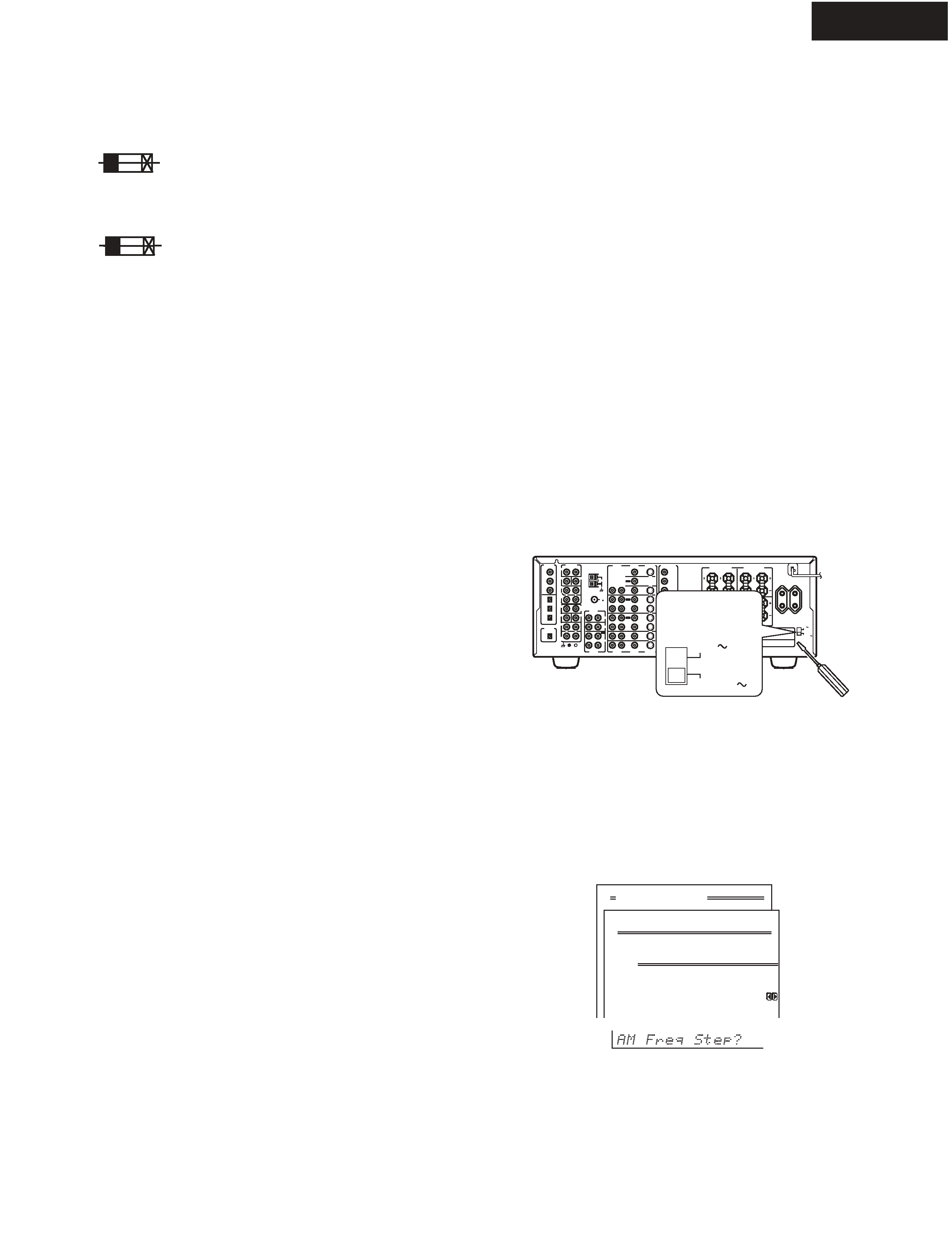
Advanced Menu
0.Hardware Setup
0-4.AM Frequency Step
a.Frequency Step
:9 kHz
6. AM Frequency Step Sub-menu
(Worldwide model Only)
a. Frequency Step
This sub-menu only appears on the worldwide model. The
setting in this sub-menu determines the increment amount
or decrement amount when adjusting the AM tuner frequency.
The initial setting is9 kHz, and this needs only to be changed
if you are using the TX-SR800 in a 10-kHz region.
5.Setting the voltage selector
(Worldwide models only)
Worldwide models are equipped with a voltage selector so
that you
supplies. Be
can set your TX-SR800 to conform with local power
sure to set this switch to match the voltage of
your area before plugging in the unit.
Determine the proper voltage for your area: 220-230 V or
the preset voltage is not correct for your area,
into the groove in the switch and slide
(220-230 V), whichever is appropriate.
AUDIO
VIDEO
S VIDEO
MONITOR
OUT
R
L
IN
IN
IN
IN
IN
ZONE 2
DVD
VIDEO 1
VIDEO 2
VIDEO 3
VIDEO 4
AUDIO
VIDEO
S VIDEO
COMPONENT
VIDEO
Y
PB
PR
OUTPUT
INPUT 1
Y
PB
PR
INPUT 2
Y
PB
PR
R
L
OUT
OUT
OUT
I R
IN
OUT
REMOTE
CONTROL
PHONO
DIGITAL
INPUT
PRE OUT
DIGITAL
OUTPUT
OPT
2
1
2
3
FRONT
SUB
SURR
R
L
AUDIO
R
L
CD
TAPE
R
L
AUDIO
1
3
GND
SURR
BACK/
ZONE 2
IN
OUT
COAX
R
L
MULTI CH
INPUT
FRONT
SUB
SURR
SURR
BACK
CENTER
R
L
R
L
AM
FM
75
VOLTAGE
SELECTOR
220-230V
120V
OPT
FRONT SPEAKERS
L
RL
R
SURR SPEAKERS
R
L
SURR BACK/
ZONE 2 SPEAKERS
CENTER SPEAKER
AC OUTLETS
SWITCHED
TOTAL 100W MAX.
AV RECEIVER
MODEL NO.
TX-SR
800
CENTER
ANTENNA
4 OHMS MIN. OR
6 OHMS MIN.
/SPEAKER
CAUTION:
SPEAKER
IMPEDANCE
SEE
INSTRUCTION
MANUAL FOR
CORRECT
SETTINGS.
120V
VOLTAGE
SELECTOR
220-230V
F6901,F6902
252199
10A-UL, Fuse <D>
252100
10A-EAK, Fuse <O>
F901
252199
10A-UL, Fuse <D/T/R>
F902
252077,
4A-SE-EAK,
252243 or
4A-SE-TL250V or
252277
4A-SE-TL250V, Fuse <O>
F903
252075,
2.5A-SE-EAK,
252241 or
2.5A-SE-TL250V or
252275
2.5A-SE-TL250V, Fuse <O>
F9501,F9502
252160 or
2.5A-UL/T-237 or
252254
2.5A-T/UL-ST2, Fuse <D>
252075,
2.5A-SE-EAK,
252241 or
2.5A-SE-TL250V or
252275
2.5A-SE-TL250V, Fuse <O>
F9503,F9504
252158 or
1.6A-UL/T-237 or
252252
1.6A-T/UL-ST2, Fuse <D>
252073,
1.6A-SE-EAK,
252239 or
1.6A-SE-TL250V or
252273
1.6A-SE-TL250V, Fuse <O>
Note:
<D>: 120V model only
<O>: Except 120V model
<T>: Worldwide model only
<R>: Chinese model only
the power supply in
120 V. If
insert a screwdriver
the switch all the way to the top (120 V) or bottom
background image
TX-SR800
EXPLODED VIEW
TX-SR800
69
68
67
69
68
67
64
37
44
43
30
42
E821
49
T901
39
U8
57
4
4
F6901
F6902
U17
4
4
30
4
U13
4
F903
U7
U39
F901
F902
55
U22
U18
U6
4
4
52
U11
U10
U38
U37
U36
U40
71
71
71
77
73
72
71
70
P901
56
4
U35
U33
U32
38
U51
P1010
U31
U1
P7201
65
62
64
35
59
34
37
36
41
97
16
81
3
28
8
9
7
U45
U48
12
U47
5
4
U41
U44
U42
10
29
U9
U46
2
U15
30
47
86
33
54
13
1
Except 120V
and Australian model
53
65
78
78
P2901
U50
31
Chenese
model
Wolrdwide
model
63
66
F9501
F9502
F9504
F9503
U23
4
Q6056
Q6066
U12
P7701
Q6062
97
U21
56
4
4
58
52
U29
U17
55
4
57
60
71
71
75 71
71
71
61
61
F9501A
Q6052
Q9422B
Q9422A
background image
TX-SR800
BLOCK DIAGRAM 2
LEFT
R IGH
T
LEFT
L
R
C
SW
SL
SR
SBL
SBR
FRONT SPEAKERS
LEFT
AC
OUTL ET
FUSE
FUS E
RIGHT
LEFT
SUBWOOFER
COOLING FAN
+5 V
VIDEO
-5 V
VIDEO
+9 V
VIDEO
RELAY
DRIVER
MAINAMP
+B1/-B1
-27V
-VP
FL AC
FL TUBE
FL AC
12VTRIGGER
+B 3
RELAY
+B 2
-15V
AUDIO
+5 V
DS P
+15V
AUDIO
MUTE
MUTE
MUTE
MUTE
RELAY
DRI VER
MUTE
VOLTAGE/CUR-
RENT SENSOR
MUTE
MUTE
MUTE
THER MAL
SENSOR
FAN
DRIVER
RI
INTERFACE
+5.6V
STAND
BY
Y
CB
CR
REMOTE SENSOR
IR OUT
I RIN
RI
T902
T901
AC IN
TONE
NJU7306G
NJU7306G
-1
-1
LED DRIVER
TC94A07F
TC94A07F
TC94A07F
MASTER VOLU ME
TC94A07F
CUT
BOOST
Z2L
MCL
BL
TL
DL
BR
TR
MC R
DR
Z2R
DSBL
MCSR
MCSBL
DSW
MCSW
DC
MC
C
DSBR
MCSBR
DSR
DSL
MCSL
SW->R
SW->L
BYPASS
C->L
SL->L
C->R
SR->R
BYPASS
BYPASS
TV-8
TV-5
POWER SW
HPEN
Zone 2 LED
Rec Out LED
TC9163
TC9164
+29dB
Power Amplifier
+29dB
11dB
11dB
+29dB
+29dB
+29dB
+29dB
+29dB
HEADPHONE
SURROUND SPEAKERS
SURROUND BACK SPEAKERS
/ZONE 2 SPEAKERS
RIGHT
RIGHT
RIGHT
CENTER
PREOUT
SURROUND
LEFT
SURROUND
RIGHT
SURROUND BACK
/ZONE 2 LEFT
SURROUND BACK
/ZONE 2 RIGHT
CENTER
MUTE
MUTE
BYPASS
MULTI CHANNEL INPUT
COMPONENT VIDEO OUTPUT
IR DE-
MODULATOR
Except 120V/Australian models
AC
OUTL ET
120V
model
Other
models
A
1
2
3
4
5
BCD

Reviews

There are no reviews of this manual yet.