SERVICE PROCEDURE
TX-SR573
1. Replacing the fuses
This symbol located near the fuse indicates that the
fuse used is show operating type, For continued protection against
fire hazard, replace with same type fuse, For fuse rating, refer to
the marking adjacent to the symbol.
Ce symbole indique que le fusible utilise est e lent.
Pour une protection permanente, n'utiliser que des fusibles de meme
type. Ce demier est indique la qu le present symbol est apposre.
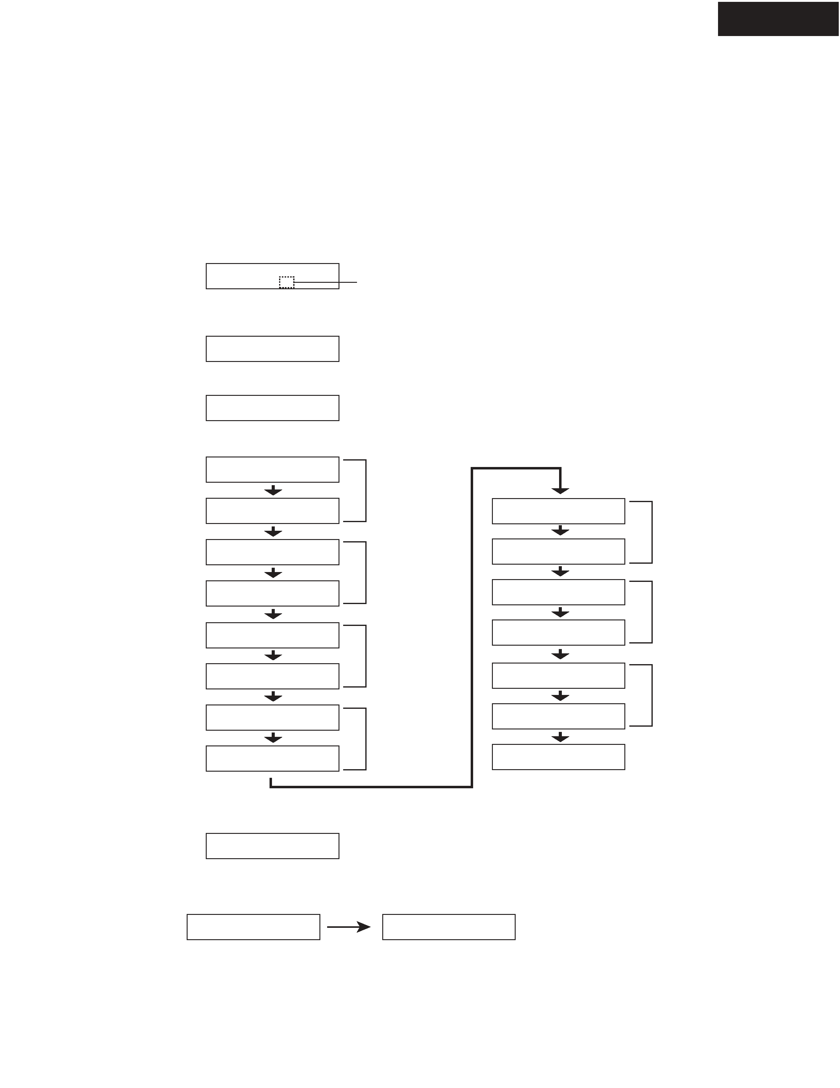
2. To initialize the unit
The AV receiver uses a battery-less memory backup system in order to retain radio presets and other settings
when it's unplugged or in the case of a power failure.
Although no batteries are required, the AV receiver must be plugged into an AC outlet in order to charge the
backup system. Once it has been charged, the AV receiver will retain the settings for several weeks,
although this depends on the environment and will be shorter in humid climates.
1. Press and the hold down the VIDEO 1/VCR button, then press the STANDBY/ON button when the unit is Power on.
2. After " Clear " is displayed, the preset memory and each mode stored in the memory, are initialized and will return to
the factory settings.
4. Memory Backup
Main microprocessor Q701 only.
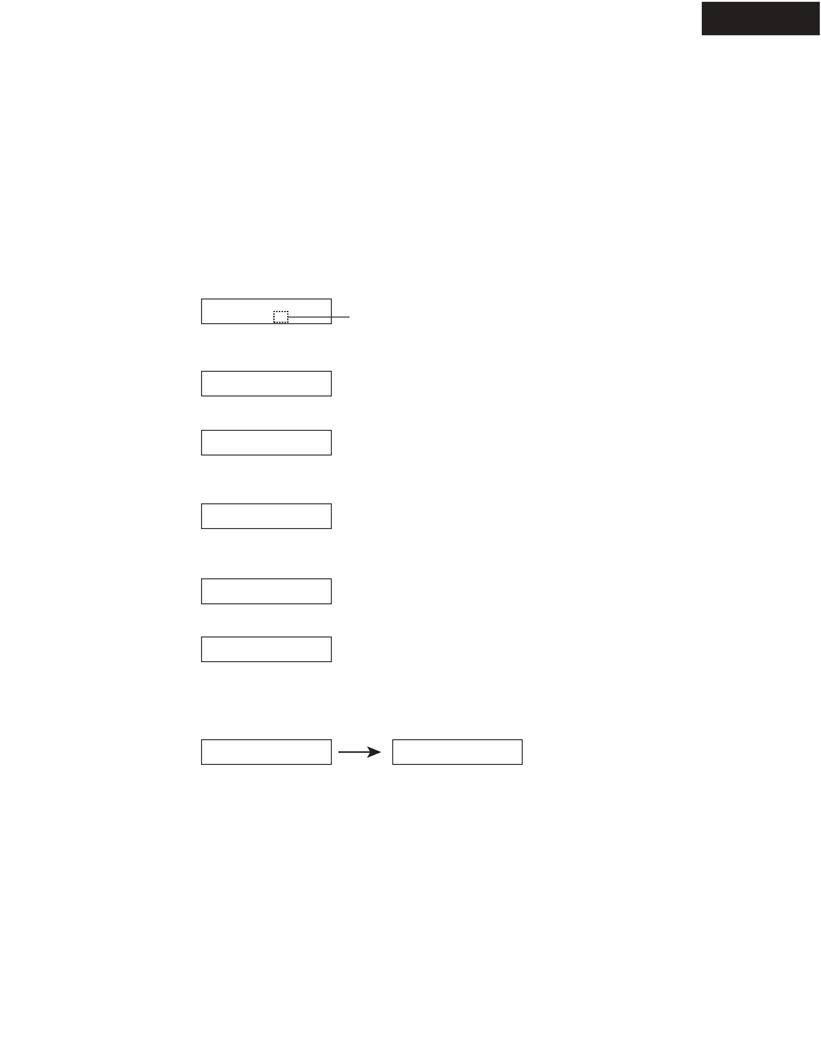
1. Press and the hold down the DISPLAY button, then press the STANDBY/ON button when the unit is Power on.
Version is displayed on FL display only for 3 seconds.
2. Press the STANDBY/ON button to Power off.
3. To check version of microprocessor
Ver.1.00/05810a
Ex.
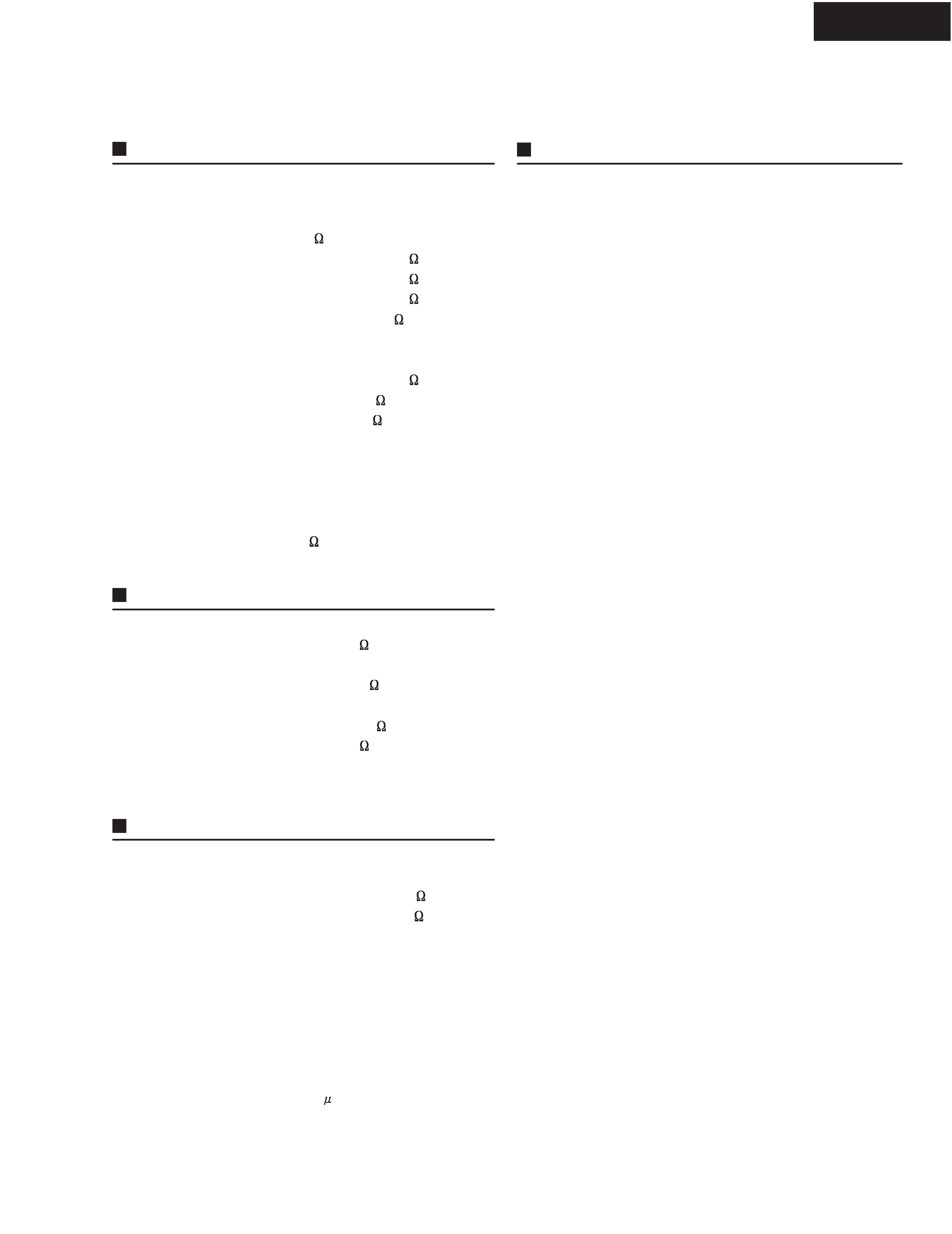
REF NO.
F901
F901 or
F903
F903 or
F6901
F6902
PART NAME
FUSE
FUSE
FUSE
FUSE
FUSE
FUSE
DESCRIPTION
8A-T/UL-ST2
8A-T/T-233
5A-T/UL-ST2
5A-T/T-233
10A-UL/T-233
10A-UL/T-233
PART NO.
252261GR
252329GR
252258GR
252326GR
252330GR
252330GR
REMARKS
!
!
!
!
!
!