ONKYO TX-SR501 Service Manual

Cover page of ONKYO TX-SR501 Service Manual

Service Manual for ONKYO TX-SR501, downloadable as a PDF file.

We also have owner's manual to this model.

Manual details

  • Immediate download after payment.
  • Delivered as a PDF file.
  • The manual has 61 pages
  • File size: 4.83 MB
  • Available language versions: English
  • Different language versions may vary sligthly in file size and page count.

We guarantee that...

  • our manuals are complete,
  • the manual includes circuit diagrams,
  • our manuals are checked with antivirus,
  • We'll issue refund if the manual is damaged, incomplete or unreadable (our refund policy)

Sample pages

Thumbnail of page 1Thumbnail of page 2Thumbnail of page 3Thumbnail of page 4
Thumbnail of page 5Thumbnail of page 6Thumbnail of page 7Thumbnail of page 8
Thumbnail of page 9
background image
TX-SR501/E
SERVICE MANUAL
SERVICE MANUAL
Ref. No. 3772
062003
120V AC, 60Hz
230-240V AC, 50Hz
120/220-230V AC, 50/60Hz
220V AC, 50Hz
AV RECEIVER
MODEL
TX-SR501/E
Black, Golden and Silver models
BMDD,BMDC
BMPP,SMPP,BMPA,GMPA
BMWT,GMWT,GMWR,GMWQ
GMGK
SAFETY-RELATED COMPONENT
WARNING!!
COMPONENTS IDENTIFIED BY MARK
ON THE
SCHEMATIC DIAGRAM AND IN THE PARTS LIST ARE
CRITICAL FOR RISK OF FIRE AND ELECTRIC SHOCK.
REPLACE THESE COMPONENTS WITH ONKYO
PARTS WHOSE PART NUMBERS APPEAR AS SHOWN
IN THIS MANUAL.
MAKE LEAKAGE-CURRENT OR RESISTANCE
MEASUREMENTS TO DETERMINE THAT EXPOSED
PARTS ARE ACCEPTABLY INSULATED FROM THE
SUPPLY CIRCUIT BEFORE RETURNING THE
APPLIANCE TO THE CUSTOMER.
Page 1
background image
TX-SR501/E
Specifications
AMPLIFIER SECTION
VIDEO SECTION
TUNER SECTION
FM
AM
GENERAL
REMOTE CONTROL
Specifications and features are subject to change without notice. Power sup-
ply and voltage vary depending on the area in which the unit is purchased.
Continuous Average Power output (FTC)
All channels:
65 watts per channel min. RMS at
8
, 2 channels driven from 20 Hz
to 20 kHz with no more than 0.08%
total harmonic distortion.
80 watts per channel min. RMS at
6
, 2 channels driven from 1 kHz
with no more than 0.1% total har-
monic distortion.
Continuous Power output (DIN)
85 watts
× 2 at 6
Maximum Power output (EIAJ)
115 watts
× 2 at 6
Dynamic power output:
160 watts
× 2 at 3
125 watts
× 2 at 4
85 watts
× 2 at 8
Total Harmonic Distortion:
0.08% at rated power
0.08% at 1 watt output
IM Distortion:
0.08% at rated power
0.08% at 1 watt output
Damping Factor:
60 at 8
Input Sensitivity and Impedance
DIGITAL INPUT (OPTICAL 1, 2):
0.5 Vp-p, 75
DIGITAL INPUT (COAXIAL):
0.5 Vp-p, 75
LINE (CD, VIDEO 1, 2, 3, TAPE):
200 mV, 47 k
Multichannel Input
(DVD FRONT L/C/R, SURR L/R):
200 mV, 47 k
(SUBWOOFER):
36 mV, 47 k
Output Level and Impedance
Rec out (TAPE, VIDEO 1):
200 mV, 470
Pre out (SUBWOOFER):
1 V, 470
Frequency Response:
10 Hz to 100 kHz,
+1/­3 dB (Direct mode)
Tone Control
Bass:
±12 dB at 50 Hz
Treble:
±12 dB at 20 kHz
Signal-to-Noise Ratio:
CD/TAPE: 100 dB
(IHF-A, Direct mode)
Muting:
­50 dB
Input Sensitivity and Impedance
VIDEO (DVD, VIDEO 1, 2, 3):
1 Vp-p, 75
S VIDEO (DVD, VIDEO 1, 2, 3):
1 Vp-p, 75
(Y)
0.28 Vp-p, 75
(C)
COMPONENT VIDEO 1, 2:
1 Vp-p, 75
(Y)
0.7 Vp-p, 75
(PB, PR)
Output Level and Impedance
VIDEO (VIDEO 1, 2, MONITOR):
1 Vp-p, 75
S VIDEO (VIDEO 1, 2, MONITOR):
1 Vp-p, 75
(Y)
0.28 Vp-p, 75
(C)
COMPONENT VIDEO OUT:
1 Vp-p, 75
(Y)
0.7 Vp-p, 75
(PB, PR)
Tuning Range
North American models:
87.50-108.00 MHz (100 kHz steps)
Other models:
87.50-108.00 MHz (50 kHz steps)
Usable Sensitivity
Mono:
11.2 dBf, 1.0 µV (75
, IHF)
0.9 µV (75
, DIN)
Stereo:
17.2 dBf, 2.0 µV (75
, IHF)
23 µV (75
DIN)
50 dB Quieting Sensitivity
Mono:
17.2 dBf, 2.0 µV (75
)
Stereo:
37.2 dBf, 20.0 µV (75
)
Capture Ratio:
2.0 dB
Image Rejection Ratio
North American models:
40 dB
Other models:
85 dB
IF Rejection Ratio:
90 dB
Signal-to-Noise Ratio
Mono:
76 dB
Stereo:
70 dB
Alternate Channel Attenuation:
55 dB
Selectivity:
50 dB (DIN)
AM Suppression Ratio:
50 dB
Total Harmonic Distortion
Mono:
0.2%
Stereo:
0.3%
Frequency Response:
30 Hz-15 kHz, ­1.0 dB
Stereo Separation:
45 dB at 1 kHz
30 dB at 100 Hz-10 kHz
Tuning Range
North American models:
530-1,710 kHz (10 kHz steps)
European & Australian models:
522-1,611 kHz (9 kHz steps)
Worldwide models:
522-1,611 kHz (9 kHz steps), or
530-1,710 kHz (10 kHz steps)
Usable Sensitivity:
30 µV
Image Rejection Ratio:
40 dB
IF Rejection Ratio:
40 dB
Signal-to-Noise Ratio:
40 dB
Total Harmonic Distortion:
0.7%
Power Supply and Power Consumption:
AC 120 V, 60 Hz
4.6 A
AC 230-240 V, 50 Hz
370 W
AC 220-230 V and 120 V switchable, 50/60 Hz
370 W
Dimensions (W
× H × D):
17-1/8"
× 5-7/8" × 14-13/16"
435
× 150 × 376 mm
Weight
North American models:
19.6 lbs., 8.9 kg
European models:
21.6 lbs., 9.8 kg
Other models:
21.8 lbs., 9.9 kg
Transmitter:
Infrared
Signal range:
Approx. 16 ft., 5 meters
Power supply:
Two "AA" batteries (1.5 V
× 2)
Page 2
background image
2. To initialize the unit
This device employs a microprocessor to perform various
functions and operations. If interference generated by an external
power supply, radio wave, or other electrical source results in
accident which causes the specified operations and functions to
operate abnormally.
To perform a result, please follow the procedure below.
1.Press and hold down the VIDEO-1 button, then press the
STANDBY/ON button.
2.After "CLEAR" is displayed, the preset memory and each
mode stored in the memory, such as surround, are
initialized and will return to the factory setting.
3. Unplug the power supply cord.
3. Safety-check out
(U.S.A. model only)
After correcting the original service problem, perform the
following safety check before releasing the set to the customer.
Leakage Current Check
Measure leakage current to a known earth ground(water pipe,
conduit, etc.) by connecting a leakage current tester between
the earth ground and exposed metal parts of the appliance
(input/output terminals, screwheads,metal overlays, etc.).
Plug the power supply cord directly into a 120V AC 60 Hz outlet
and turn Standby switch on. Any current meausred must not
exceed 0.5mA.
1. Replacing the fuses
This symbol located near the fuses indicates that the
fuse used is fast operating type. For continued protection against
fire hazard, replace with same type fuse. For fuse rating refer to
the marking adjacent to the symbol.
Ce symbole indique que le fusible utlise est a rapide.
Pour une protection permanente, n'untiliser que fusibles de
meme type. Ce darnier est la qu le present symbol est
appse.
4.Setting the voltage selector (Worldwide models
only)
Worldwide models are equipped with a voltage selector to conform
with local power supplies. Be sure to set this switch to match the
voltage of the power supply in your area before plugging in the unit.
Determine the proper voltage for your area: 220-230 V or 120 V. If
the preset voltage is not correct for your area, insert a screwdriver
into the groove in the switch. Slide the switch all the way to the
upper (120 V) or to the lower (220-230 V), whichever is appropriate.
5.Setting the AM tuning step frequency
(Worldwide models only)
CIRCUIT NO. PART NO.
DESCRIPTION
Note: <D>:120V model only
<O>: Other models except 120V model
<T>: Asian model only for 230V
<R>: Chinese model only
<Q>: Hongkong model only
L
R
R
L
R
L
ANTENNA
FM
75
AM
FRONT
SPEAKERS A
FRONT
SPEAKERS B
SURROUND
SPEAKERS
CENTER
SPEAKER
R
L
SURROUND BACK
SPEAKER
REMOTE
CONTROL
IN
IN
IN
OPTICAL
COAXIAL
1
2
IN
IN
IN
IN
FRONT
SURR
CENTER
SUB
WOOFER
OUT
OUT
OUT
DIGITAL INPUT
VIDEO 2
VIDEO 1
DVD
MONITOR
OUT
VIDEO
S VIDEO
DVD
TAPE
CD
L
R
VIDEO 2
VIDEO 1
SUBWOOFER
PRE OUT
VIDEO 1
/2/3
IN
DVD IN
COMPONENT VIDEO
Y
PB
PR
OUT
L
R
SWITCHED
100W MAX.
AC OUTLET
120V
VOLTAGE
SELECTOR
220-230V
120V
VOLTAGE
SELECTOR
220-230V
If you are using the Worldwide model (i.e., your TX-SR501/
TX-SR501E has a VOLTAGE SELECTOR on the rear
panel), you need to set the AM tuning interval for compati-
bility with AM broadcasts in your particular country. The ini-
tial setting is 9 kHz.
North America: 10 kHz
Other countries: 9 kHz
Note:
All presets are deleted when you change this setting.
To set the AM tuning interval, while
holding down the [TUNER] button,
press the [MEMORY] button.
TUNER
FM MODE
MEMORY
CLEAR
F6901,F6902
252198 or
8A-UL or
252261
8A-T/UL-ST2 <D>
252099
8A-EAK ,Fuse <O>
F901
252166 or
6.3A-UL/T-237 or
252260
6.3A-T/UL-ST2,Fuse <D/T/Q/R>
F902
252076,
3.15A-SE-EAK,
252242 or
3.15A-SE-TL250V or
252276
3.15A-SE-TL250V <O>
F903
252075,
2.5A-SE-EAK,
252241 or
2.5A-SE-TL250V or
252275
2.5A-SE-TL250V,Fuse <O>
TX-SR501/E
SERVICE PROCEDURES
Page 3
background image
TX-SR501/E
Controls & Connectors--Continued
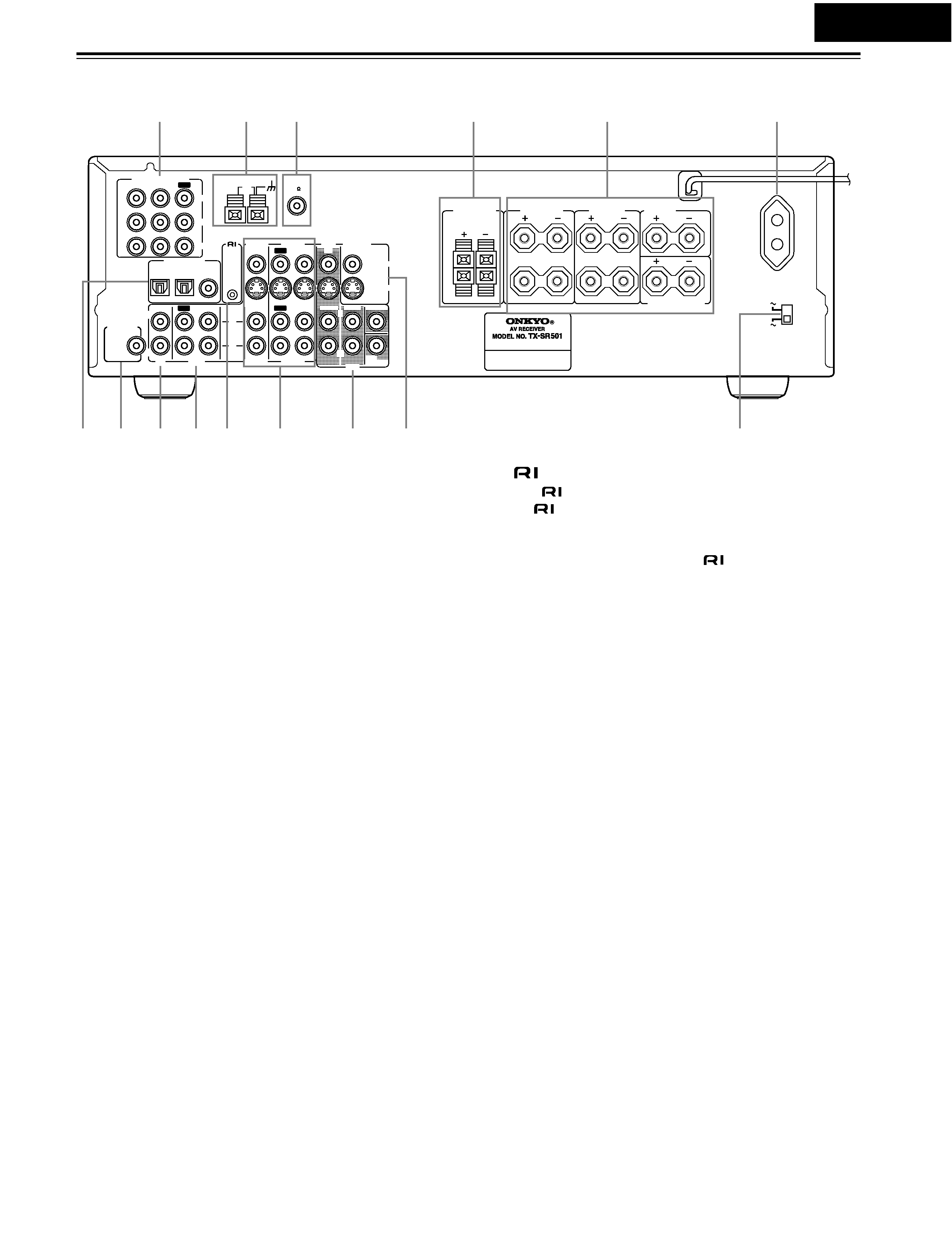
Rear Panel
A COMPONENT VIDEO (10, 12, 14, 16)
These RCA/phono connectors can be used to connect a TV,
DVD player, or other AV component with component video
inputs and outputs.
B AM ANTENNA (22, 23)
These push terminals are for connecting an AM antenna.
C FM ANTENNA (22, 23)
This connector is for connecting an FM antenna.
D FRONT SPEAKERS B (21)
These push terminals are for connecting speaker set B.
E FRONT SPEAKERS A, SURROUND SPEAKERS,
CENTER SPEAKER & SURROUND BACK
SPEAKER (21)
These terminal posts are for connecting speaker set A, includ-
ing the front, surround, center, and surround-back speakers.
They accept bare wires or banana plugs (European models
don't accept banana plugs).
F AC OUTLET (11)
This switched AC outlet can be used to supply power to
another AV component. The connector type depends on the
country in which you purchased your TX-SR501/
TX-SR501E.
G DIGITAL INPUT OPTICAL 1, 2 & COAXIAL (10,
13, 14, 16­18)
These optical and coaxial connectors can be used to connect a
CD, DVD, or LD (laser disc) player, or other AV component
with digital outputs.
H SUBWOOFER PRE OUT (21)
This RCA/phono connector can be used to connect an active
subwoofer.
I CD IN (10, 17)
These RCA/phono connectors can be used to connect a CD
player with analog outputs.
J TAPE IN/OUT (10, 17, 18)
These RCA/phono connectors can be used to connect a cas-
sette recorder, MiniDisc recorder, or other recorder with ana-
log inputs and outputs.
K
(19)
This
(Remote Interactive) connector can be connected to
the
connector on another Onkyo AV component, for
example, a CD player, DVD player, or cassette recorder. The
TX-SR501/TX-SR501E's remote controller can then be used
to control that component. To use
, you must make an ana-
log RCA/phono connection between your TX-SR501/
TX-SR501E and the other AV component, even if they are
connected digitally.
L VIDEO 1 IN/OUT & VIDEO 2 IN (10, 14­16, 39)
These connectors can be used to connect a VCR or other AV
component. There are RCA/phono connectors for connecting
to stereo analog audio inputs and outputs, and S-Video and
composite video (RCA/phono) connectors for connecting to
video inputs and outputs.
M DVD IN/MULTI CH INPUT (10, 12, 13)
The FRONT, SURR, CENTER, and SUBWOOFER RCA/
phono connectors can be used to connect AV components with
multiple analog audio outputs, including DVD players with
individual 5.1 surround analog outputs. There's an S-Video
input and composite video (RCA/phono) input for connecting
the video signal.
N MONITOR OUT (10, 12)
These S-Video and composite video (RCA/phono) outputs can
be connected to the video input on your TV or projector.
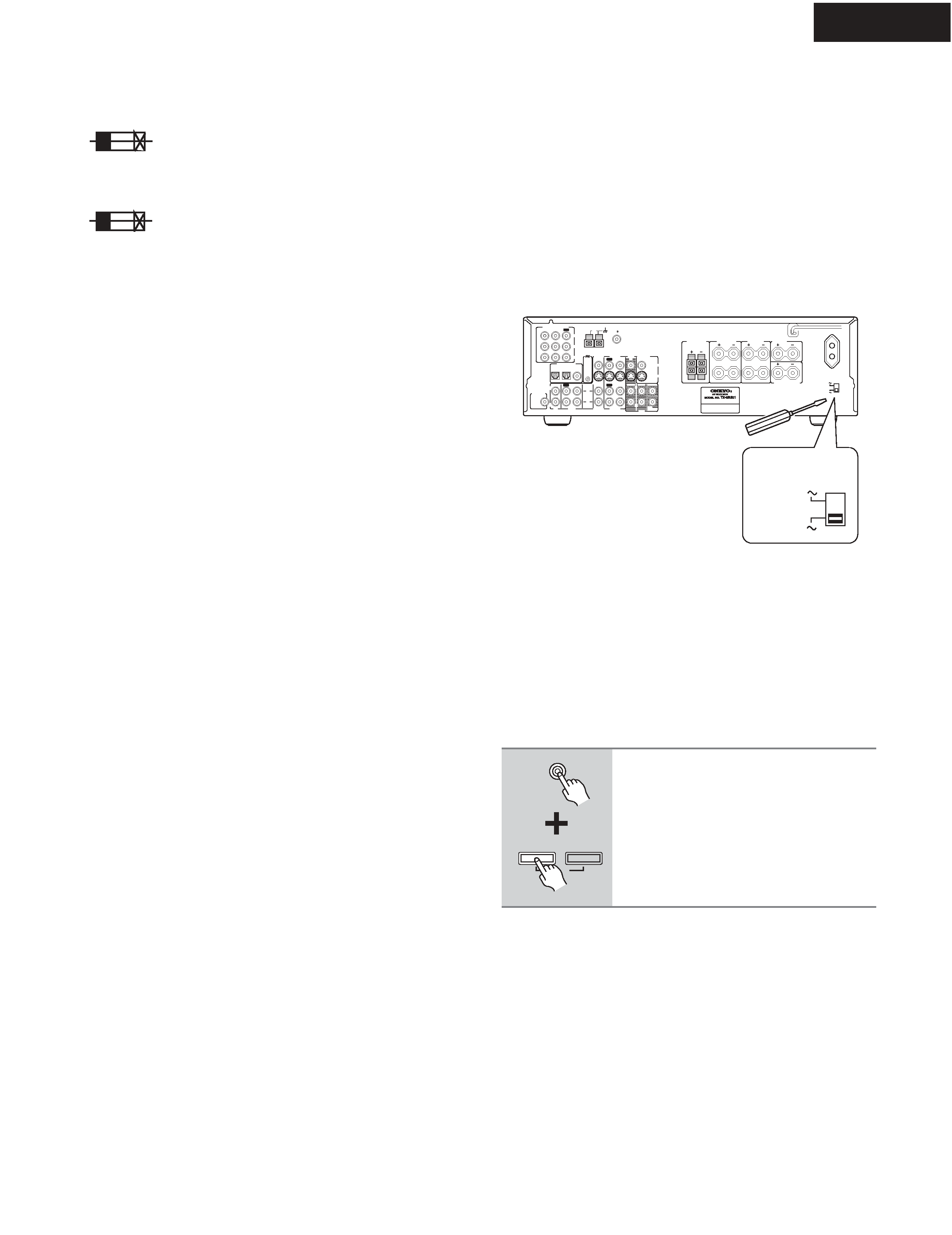
O VOLTAGE SELECTOR (Worldwide model only)
(5)
This voltage selector provides compatibility with power sys-
tems around the world.
Tip:
A turntable with a built-in preamp can be connected to a pair of
unused TX-SR501/TX-SR501E analog inputs. To connect a
turntable without a built-in preamp, you'll need a commer-
cially available phono preamp. See pages 17 and 18 and the
instructions supplied with your phono preamp and turntable for
more information.
L
R
R
L
R
L
ANTENNA
FM
75
AM
FRONT
SPEAKERS A
FRONT
SPEAKERS B
SURROUND
SPEAKERS
CENTER
SPEAKER
R
L
SURROUND BACK
SPEAKER
REMOTE
CONTROL
IN
IN
IN
OPTICAL
COAXIAL
1
2
IN
IN
IN
IN
FRONT
SURR
CENTER
SUB
WOOFER
OUT
OUT
OUT
DIGITAL INPUT
VIDEO 2
VIDEO 1
DVD
MONITOR
OUT
VIDEO
S VIDEO
DVD
TAPE
CD
L
R
VIDEO 2
VIDEO 1
SUBWOOFER
PRE OUT
VIDEO 1
/2/3
IN
DVD IN
COMPONENT VIDEO
Y
PB
PR
OUT
L
R
SWITCHED
100W MAX.
AC OUTLET
120V
VOLTAGE
SELECTOR
220-230V
1
6
78
9 J K
M
N
O
45
3
2
L
Worldwide
model only
Page 4
background image
TX-SR501/E
Front Panel
A POWER switch (24)
The North American model doesn't have this switch.
This is the main power switch. When set to OFF, the
TX-SR501/TX-SR501E is completely shutdown. When set to
ON, the TX-SR501/TX-SR501E is in Standby mode and the
STANDBY indicator lights up.
Don't turn on the power until you've completed, and double
checked all connections.
Note:
Turning on the TX-SR501/TX-SR501E may cause a momen-
tary power surge that might interfere with other electrical
equipment on the same circuit. If this is a problem, plug the
TX-SR501/TX-SR501E into a different branch circuit.
B STANDBY/ON button (24)
This button is used to set the TX-SR501/TX-SR501E to On or
Standby. For models with a POWER switch, this button has no
effect unless the POWER switch is set to ON.
C STANDBY indicator (24)
This indicator lights up when the TX-SR501/TX-SR501E is in
Standby mode, and it flashes while a signal is being received
from the remote controller.
D DIMMER button (32)
This button is used to adjust the display brightness.
E DIGITAL INPUT button (24)
This button is used to assign the digital inputs.
F SUBWOOFER MODE button (25)
This button is used to select the Subwoofer modes.
STANDBY/ON
PHONES
MASTER VOLUME
VIDEO
2
TAPE
TUNER
C D
VIDEO
3
DVD
AB
SPEAKERS
DIMMER
SURROUND
VIDEO
1
VCR
AUDIO
SELECTOR
DSP
STEREO
STANDBY
DISPLAY
AUDIO ADJUST
SPEAKER ADJUST
FM MODE
SUBWOOFER
MODE
DIGITAL INPUT
MEMORY
DIRECT
S VIDEO
AUDIO
VIDEO
L
R
TUNING
CLEAR
PRESET/ADJUST
VIDEO
3 INPUT
OQ
R
T
U
S
P
23 4 5
8
9
J
K
M
L
6
N
7
North American Model
STANDBY/ON
PHONES
MASTER VOLUME
VIDEO
2
TAPE
TUNER
C D
VIDEO
3
DVD
AB
SPEAKERS
DIMMER
SURROUND
VIDEO
1
VCR
AUDIO
SELECTOR
DSP
STEREO
STANDBY
DISPLAY
AUDIO ADJUST
SPEAKER ADJUST
FM MODE
SUBWOOFER
MODE
DIGITAL INPUT
MEMORY
DIRECT
S VIDEO
AUDIO
VIDEO
L
R
TUNING
CLEAR
PRESET/ADJUST
VIDEO
3 INPUT
OQ
R
T
U
S
P
23 4 5
8
9
J
K
M
L
6
N
7
OFF
ON
POWER
1
Other Models
Page 5

Reviews

There are no reviews of this manual yet.