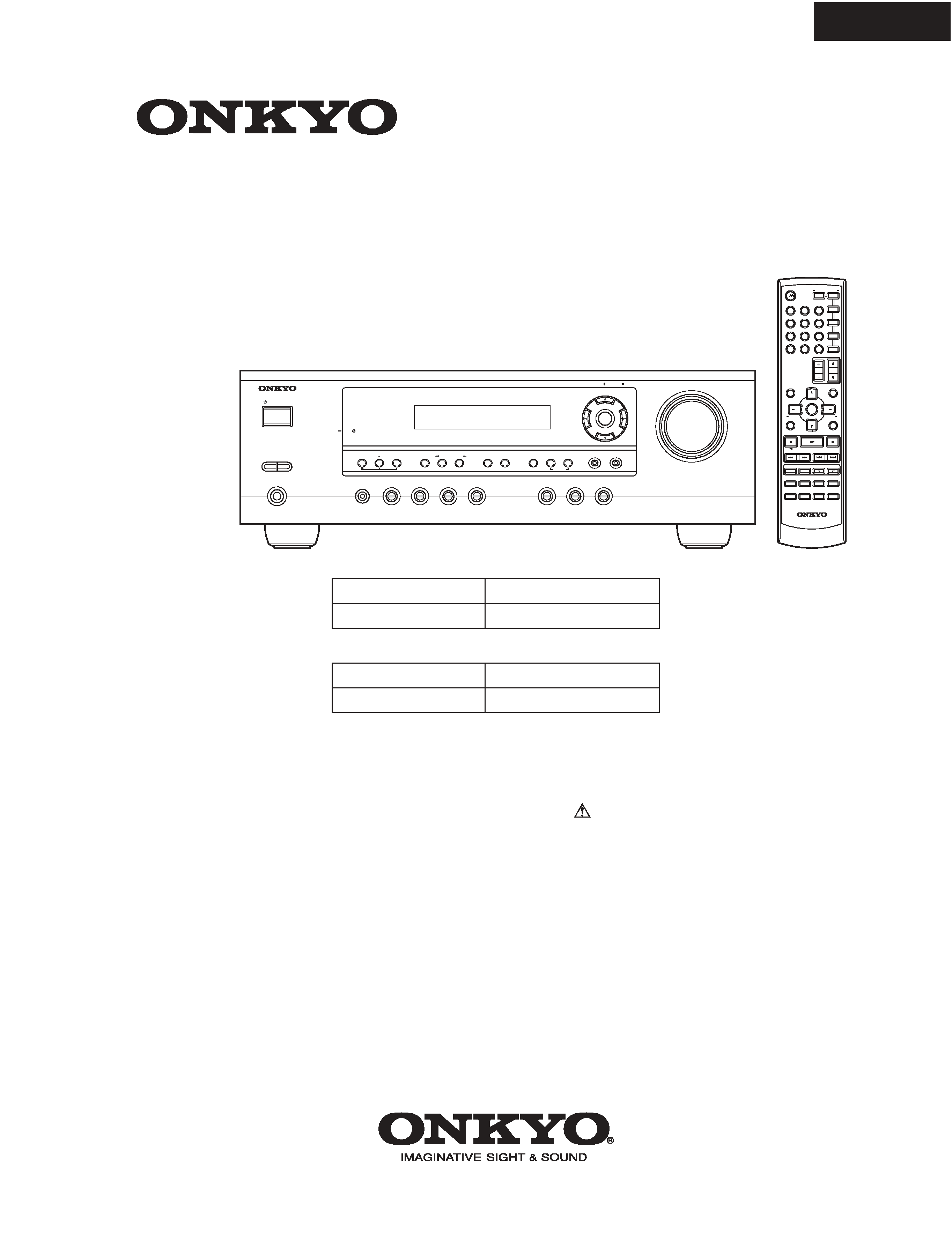
TX-SR304/304E
OPERATION CHECK-3
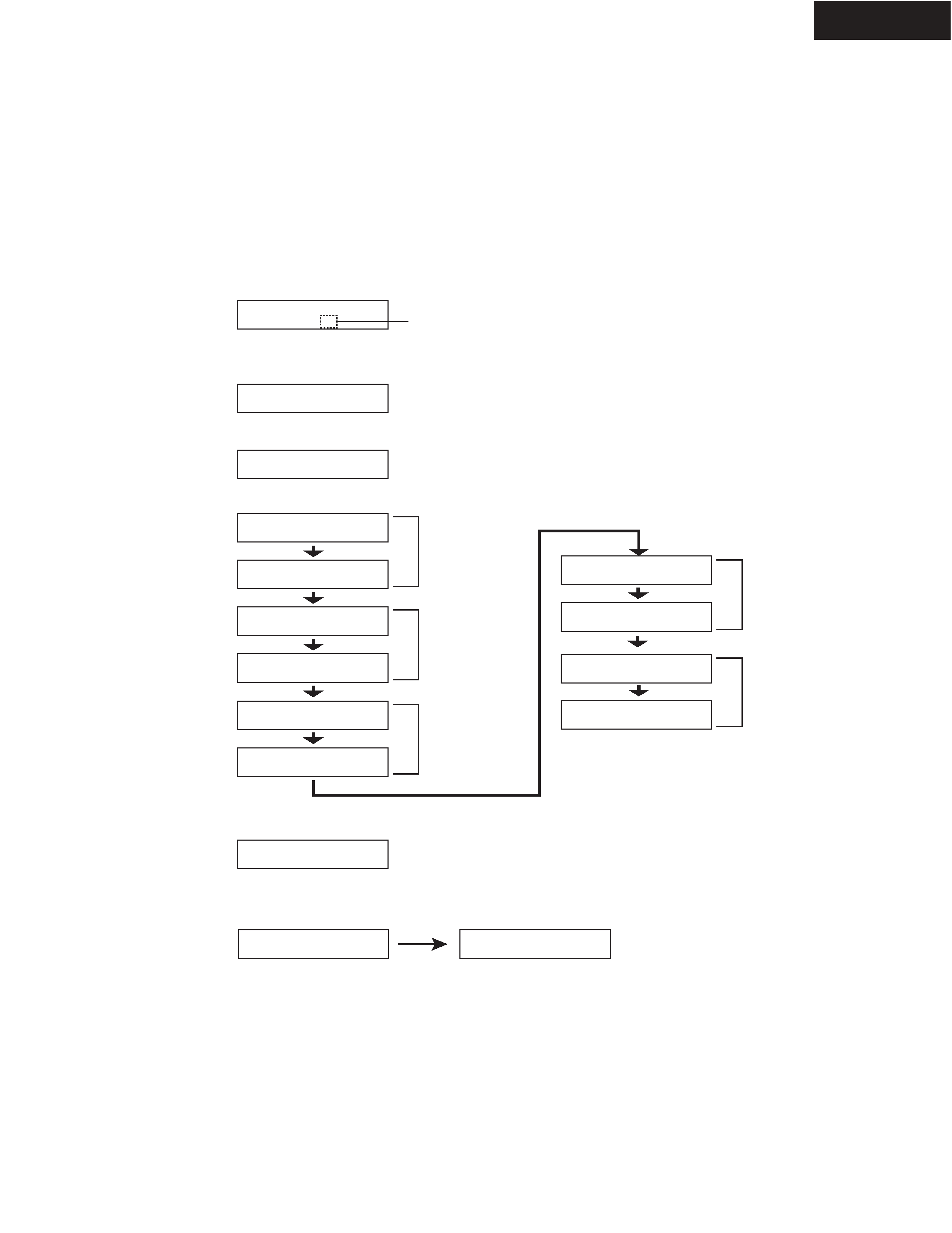
THERMAL SENSOR PROTECT
DEBUG MODE-1
Ver. 1.01/05Z28b
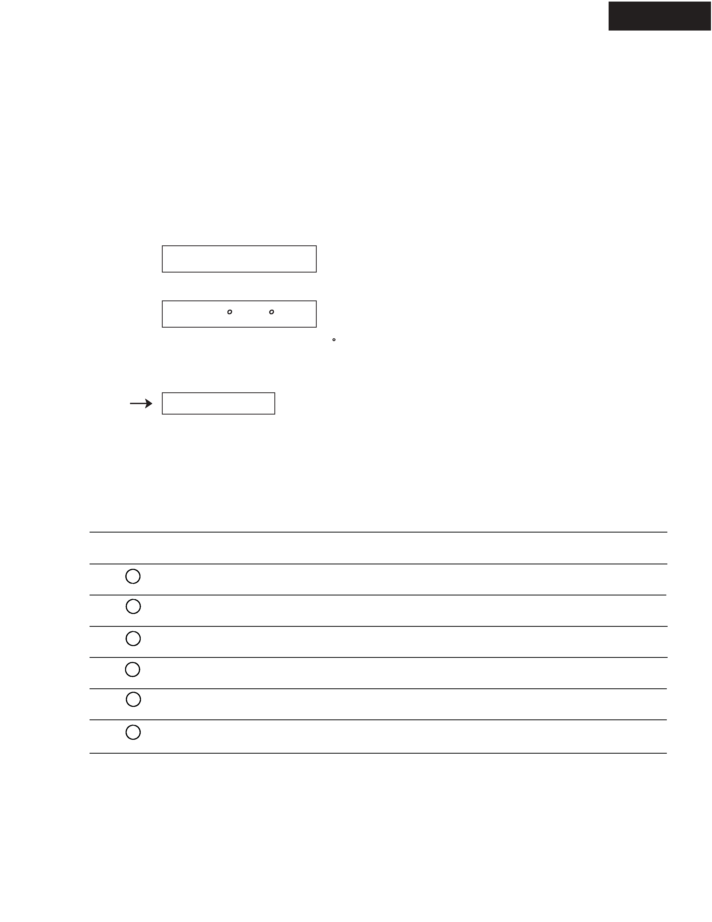
<Ex.>
<Ex.>
T: 25 C/ 77 F
Turn off
[Procedure]
<Note> No output. No input.
[When]
1. Exchange power IC (Q6001, Q6002).
2. Exchange power amplifier PC board ass'y (NAAF-8745).
1. Press and hold down DISPLAY button, then press STANDBY/ON button when the unit is powered on.
The microprocessor version will be displayed for 3 seconds.
4. Press STANDBY/ON button.
3. Confirm that the displayed temperature is within +/-20 C from the ambient temperature.
This debug mode will help in analysing digital audio no sound trouble.
Check information on FL display and the related devices or circuits.
For details of the digit number and information on FL display, refer to next page.
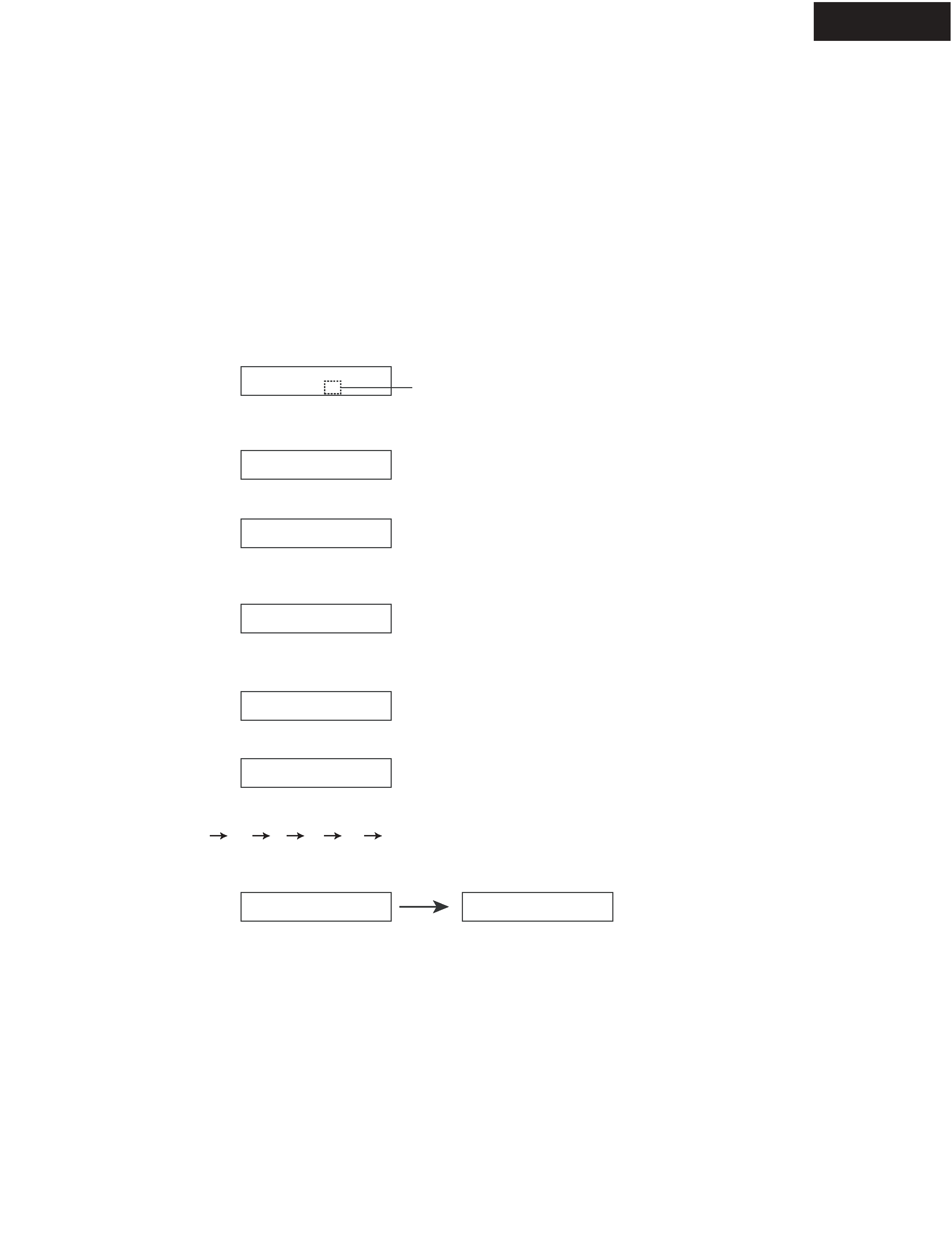
Symptom on Display
Cause
Check
"E" is displayed
No input signal to DIR
Related devices from digital input to Q301
Displayed freq. is different
from input signal freq.
No input signal to DIR
Related devices from digital input to Q301
Displayed format is different
from input signal format
No input signal to DIR
Related devices from digital input to Q301
Digit No. on FL
5
3
1
Displayed format is different
from input signal format
Input signal to DSP is no good
Related devices from Q301 to Q201
"x" is displayed
Interface between DSP and
Microprocessor is no good
Related devices from Q701 to Q201
This identifies IC which
outputs error
The IC outputs error to main
microprocessor
Q5001, Q201, Q301 & related devices
9
8
10
2. Press TONE button while the version is displayed.