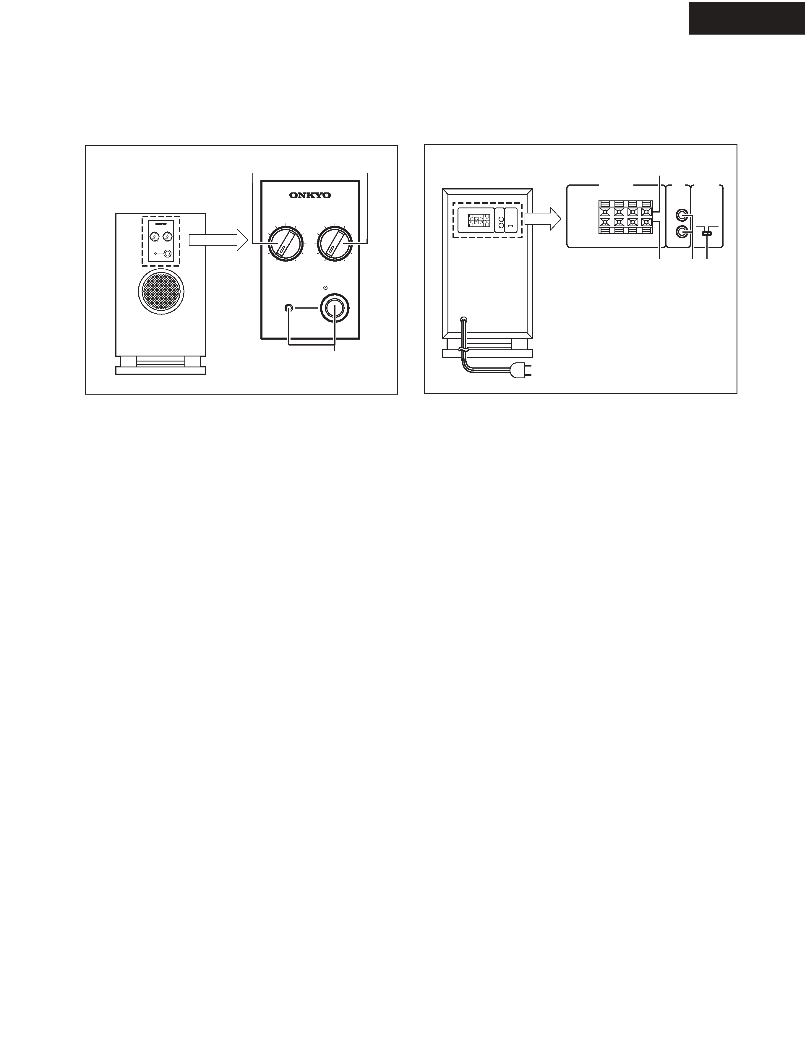
ONKYO SL-105 Service Manual

Cover page of ONKYO SL-105 Service Manual

Service Manual for ONKYO SL-105, downloadable as a PDF file.

Manual details

  • Immediate download after payment.
  • Delivered as a PDF file.
  • The manual has 19 pages
  • File size: 0.92 MB
  • Available language versions: English
  • Different language versions may vary sligthly in file size and page count.

We guarantee that...

  • our manuals are complete,
  • the manual includes circuit diagrams,
  • our manuals are checked with antivirus,
  • We'll issue refund if the manual is damaged, incomplete or unreadable (our refund policy)

Sample pages

Thumbnail of page 1Thumbnail of page 2Thumbnail of page 3Thumbnail of page 4
Thumbnail of page 5Thumbnail of page 6Thumbnail of page 7Thumbnail of page 8
Thumbnail of page 9
background image
SL-105
Ref. No.3709
SAFETY-RELATED COMPONENT
WARNING!!
COMPONENTS IDENTIFIED BY MARK
ON THE
SCHEMATIC DIAGRAM AND IN THE PARTS LIST ARE
CRITICAL FOR RISK OF FIRE AND ELECTRIC SHOCK.
REPLACE THESE COMPONENTS WITH ONKYO
PARTS WHOSE PART NUMBERS APPEAR AS SHOWN
IN THIS MANUAL.
MAKE LEAKAGE-CURRENT OR RESISTANCE
MEASUREMENTS TO DETERMINE THAT EXPOSED
PARTS ARE ACCEPTABLY INSULATED FROM THE
SUPPLY CIRCUIT BEFORE RETURNING THE
APPLIANCE TO THE CUSTOMER.
082001
SERVICE MANUAL
SERVICE MANUAL
SUB WOOFER SYSTEM
SL-105 / HTP-2
MPP
230-240V AC, 50Hz
MDT
120V AC, 60Hz
MGT
220-230V AC, 50/60Hz
Black color : MPP model
Yellow color : MDT, MGT models
SL-105
POWERED SUBWOOFER
D-L5 x 5
SATELLITE SPEAKERS
background image
SL-105
SERVICE NOTE
1. Replacing the fuses
This symbol located near the fuses indicates that the fuse used is
fast operating type. For continued protection against fire hazard, re-
place with same type fuse. For fuse rating refer to the marking adja-
cent to the symbol.
Ce symbole indique que le fusible utlise est a rapide. Pour une pro-
tection permanente, n'untiliser que fusibles de meme type. Ce darni-
er est la qu le present symbol est appse.
CIRCUIT NO. PART NO. DESCRIPTION
CIRCUIT NO. PART NO.
DESCRIPTION
F901,F903
252069 or
0.8A-SE-EAK or
252236
800MA-SE-TL250V <MPP,MGT>
F902
252159 or
2A-UL/T-237 or
252253
2A-T/UL-ST2 <MDT>
2. Safety-check out
After correcting the original service problem, perform the following
safety check before releasing the set to the customer. Connect the in-
sulating-resistance tester between the plug of power supply cord and
screw on the back panel.
Specifications: 3.3Mohm
background image
SL-105
PANEL VIEW
Front panel
A Low-level input jacks (LINE INPUT)
Connect these jacks to the LINE OUT jacks of the
amplifier etc.
B Auto standby switch (AUTO STANDBY)
This switch is used to turn on and off the auto standby
function.
ON: This activates the auto standby function.
If a constant level signal is not received from the
amplifier (or receiver) over a period of a few minutes,
the SL-105 automatically enters the standby state. If a
constant level signal is later received from the amplifier
(or receiver), the power is automatically turned back on.
OFF: Deactivates the auto standby function.
Notes:
The auto standby function operates on the existence
or absence of a constant level input signal. If the auto
standby function does not operate properly, try
slightly increasing (or decreasing) the output level of
the amplifier or receiver. (Note that output levels of
some amplifiers and receivers cannot be adjusted.
For more details regarding your components, refer to
the instruction manual supplied with them.)
If noise from peripheral components causes the
incorrect operation of the auto standby function, or if
outputting low volumes (i.e., during the nighttime)
causes the auto standby function to activate, turn off
the auto standby function.
The auto standby function only operates while the
power switch for the SL-105 is turned on.
C Speaker-level input terminals
(INPUT FROM AMP/RECEIVER)
Connect these input terminals to the speaker output
terminals of your amplifier or receiver.
D Speaker-level output terminals
(OUTPUT TO SPEAKERS)
The speaker-level signal to the front speakers is output
from these terminals.
1
Power switch (POWER) and indicator
Pressing this button turns the power on (the indicator
lights). Pressing the button again turns the power off
(the indicator goes out).
Red:
Unit is in standby mode
Green:
Unit is in operation
2
Frequency adjusting knob (FREQUENCY)
Use this knob to select the high-frequency range at
which you wish to cut off the signal to the subwoofer.
You can select any frequency between 50 Hz and 200
Hz depending on the characteristics of the speaker
system being used with the SL-105.
3
Output level adjusting knob (OUTPUT LEVEL)
Use this knob to adjust the output level of the
subwoofer.
Rear panel
R
SPEAKER LEVEL
INPUT
FROM
AMP/RECEIVER
AUTO STANDBY
LINE
INPUT
L
R
OFF
ON
OUTPUT
TO SPEAKERS
(MONO)
+
_
L
+
_
R
+
_
L
+
_
SL-105
C
DA B
To AC outlet
FREQUENCY
OUTPUT LEVEL
MIN
MAX
50Hz
200Hz
POWER
POWERED SUBWOOFER
SL-105
1
23
Subwoofer SL-105
*
*
*
background image
SL-105
P535
E901
S7
S7
S7
S7
S4
S4
S4
S4
S8
S8
S8
S8
S2
S1
EXPLODED VIEW
(CABINET SECTION)
S10
S3
Indicated in the exploded view of
an amplifier section.
S9
background image
SL-105
A1
A2
A2
A4
A5
A5
A5
A5
A2
A8
A15
A18
A18
A20
A30
A41
A42
A49
A48
Q515
R602
Q515A
Q516B
Q516
Q541
Q951
Q952
T901
U1
U4
U5
U6
S7
A4
A42
A4
A42
A43
A43
A52
A55
E811
F901
P901
U2
U3
U8
U7
S7
S7
S7
S7
S7
S7
S7
S6
S5
S3
CHASSIS EXPLODED VIEW
(AMPLIFIER SECTION)

Reviews

There are no reviews of this manual yet.