SKW-120/HTP-120
PANEL VIEW
(Front left/right, Surround left/right)
The badge can be rotated depending on the angle you position the
speaker.
The badge can be rotated depending on the angle you position the
speaker.
The satellite speakers (D-120) and the center speaker (D-120C)
have colored labels on the backs for easy identification. Match
the color of the label with the corresponding speaker cable when
connecting the speakers. The DR-S2.2 SPEAKER terminals are
also colored to match the corresponding speaker cable.
Connect the cable with a colored line to the negative (-)
terminal.
The label colors and the corresponding speakers are as
follows:
Front left speaker and speaker cable:
White
Front right speaker and speaker cable:
Red
Center speaker and speaker cable:
Green
Surround left speaker and speaker cable:
Blue
Surround right speaker and speaker cable: Grey
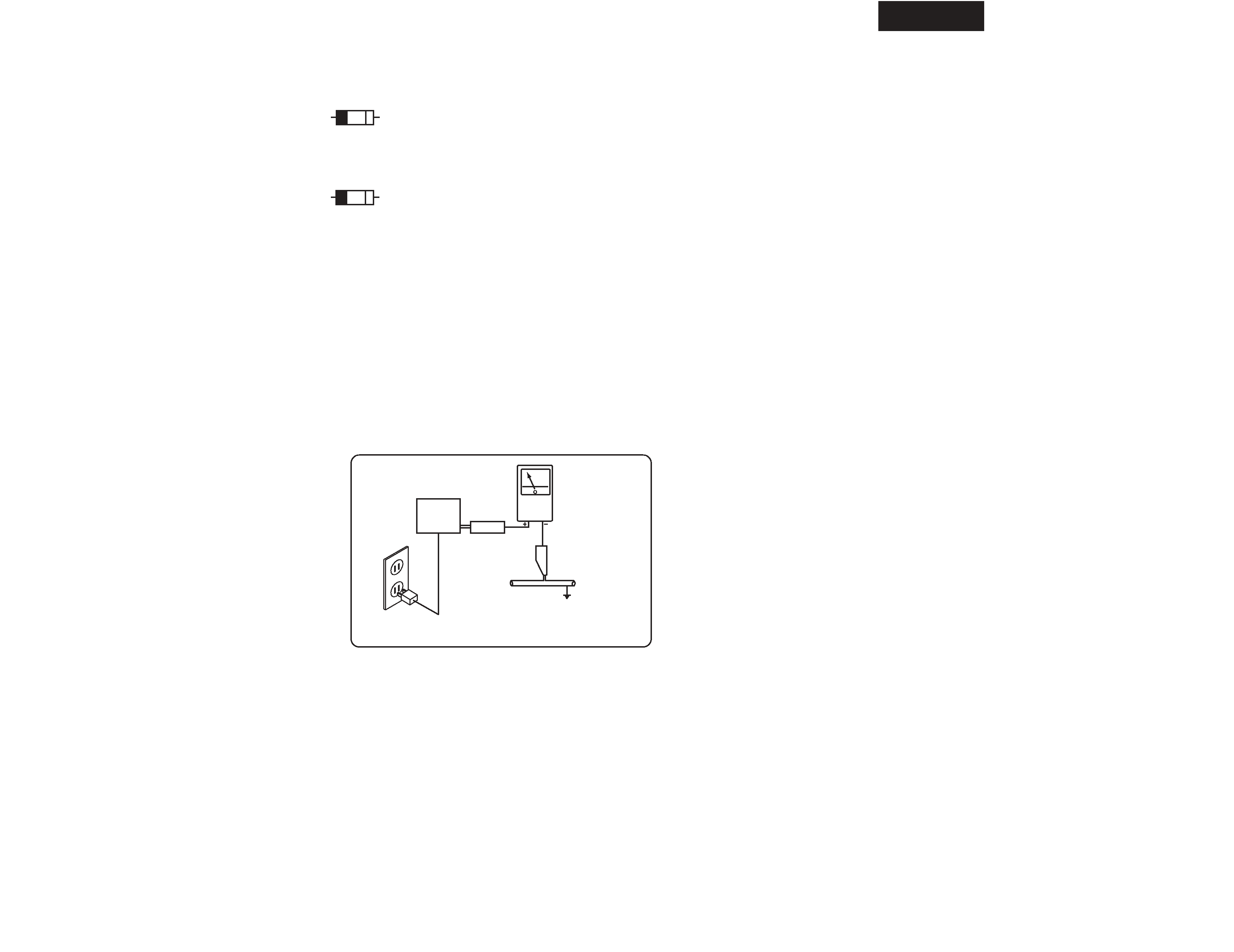
A. LINE INPUT (input jack)
Connect this jack to the SUBWOOFER PREOUT jack of
the DR-S2.2.
B. Indicator
The indicator changes from red to green when the
subwoofer receives a signal.
C. OUTPUT LEVEL (Output level adjusting knob)
Use this knob to adjust the output level of the subwoofer.
Front
Rear
To AC outlet
AB
C
LINE
INPUT
OUTPUT LEVEL
MAX
MIN
RED : STANDBY
GREEN : ON
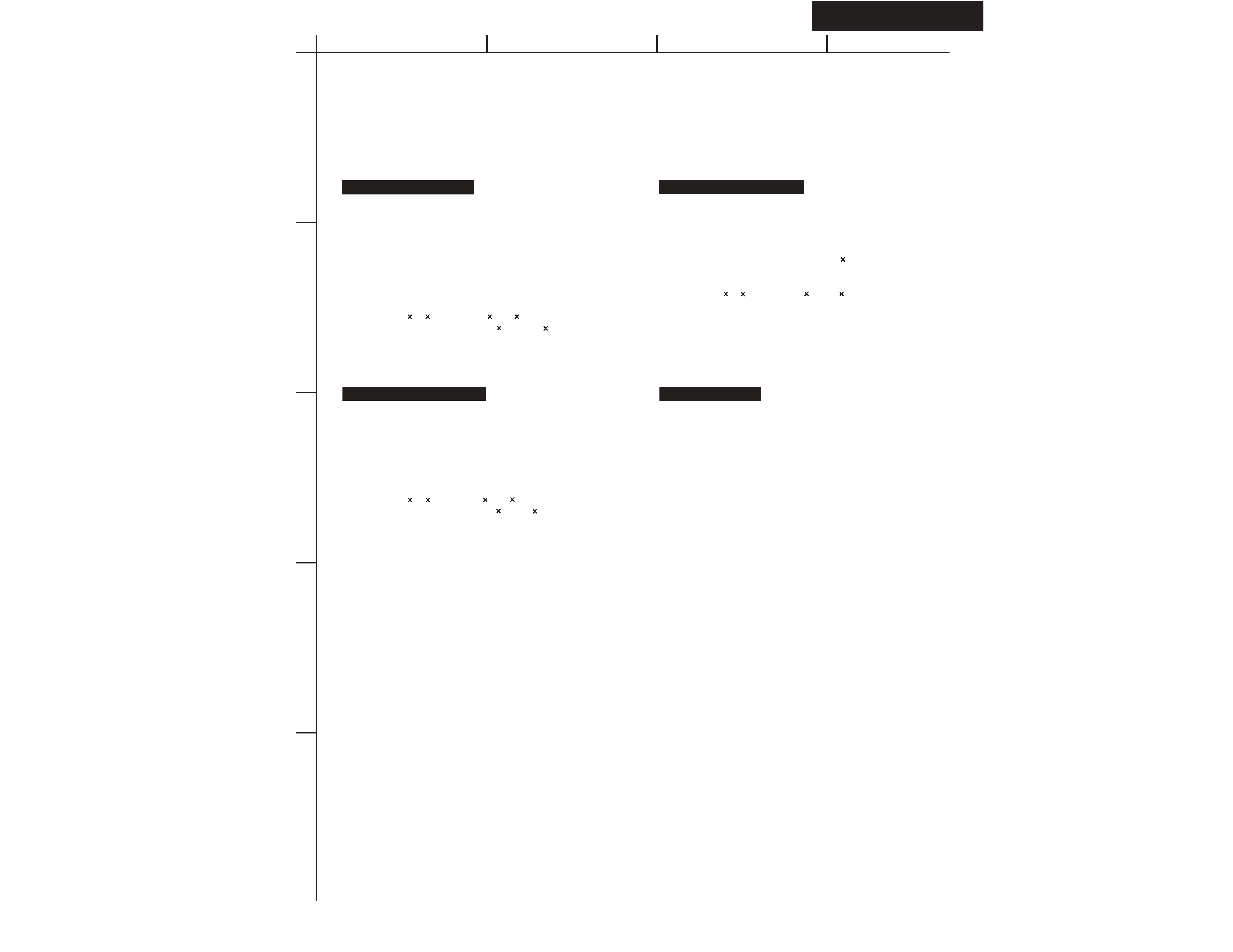
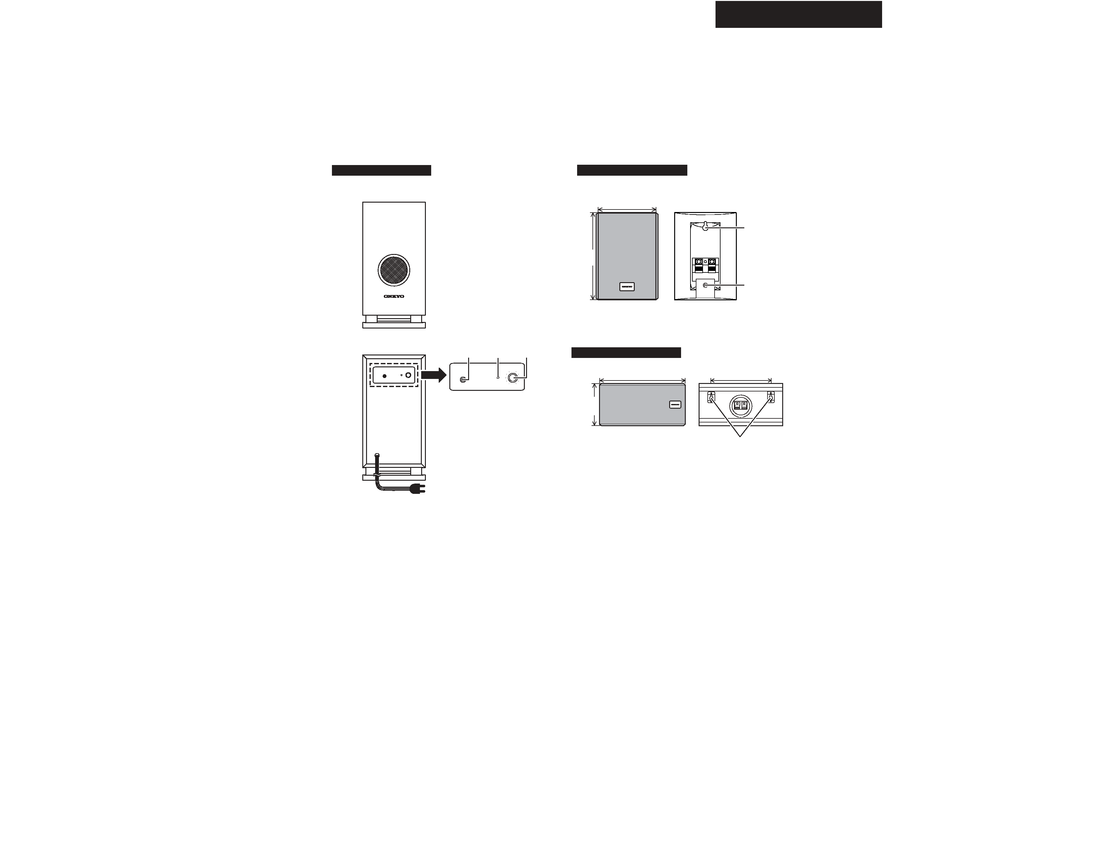
85mm (3-3/8")
120mm
(4-3/4")
265mm (10-7/16")
130.5mm
(5-1/8")
180mm (7-1/16")
Key hole
Screw hole
for a
speaker
stand
Key holes
Subwoofer SKW-120
Satellite speakers D-120
Center speaker D-120C