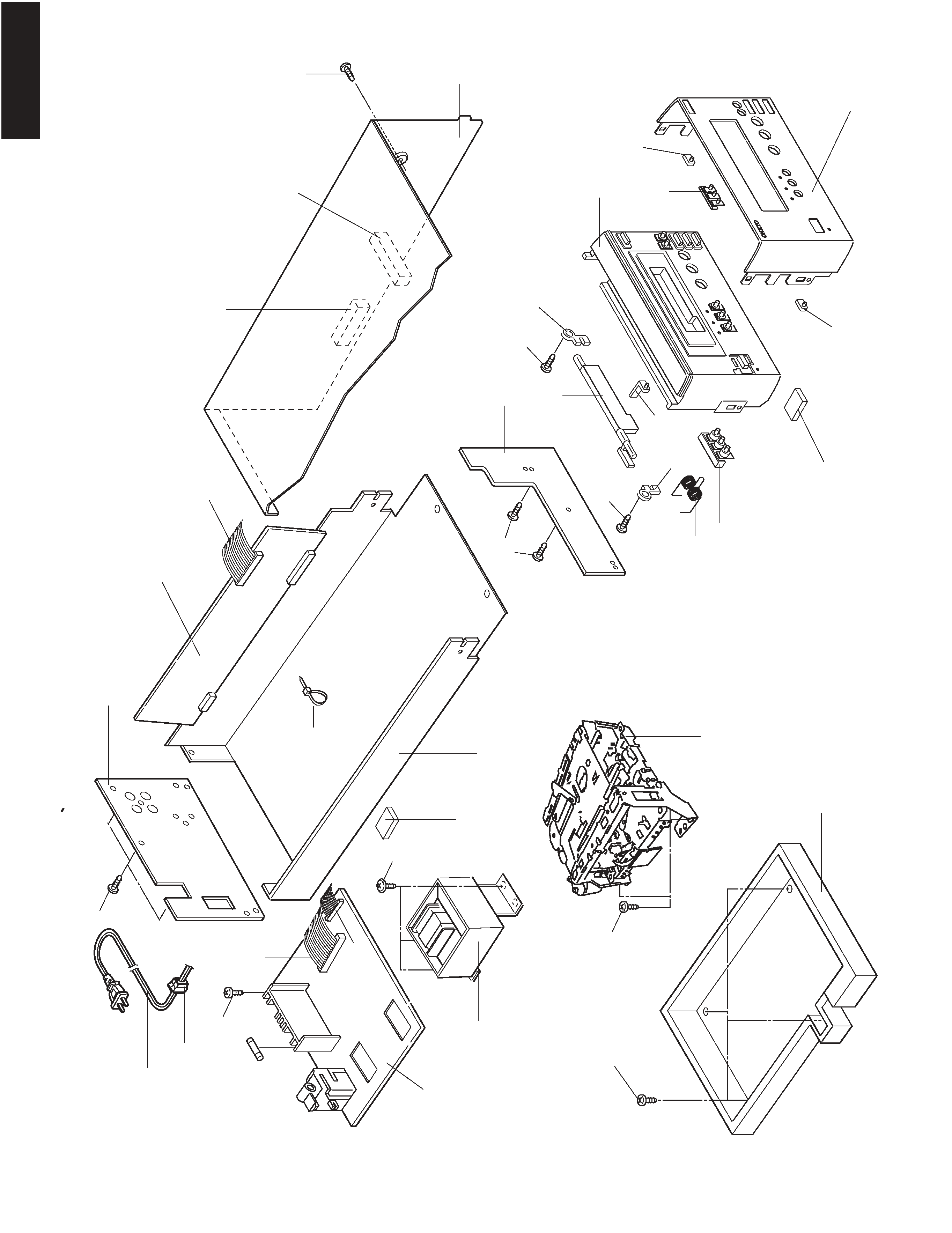
ONKYO K-501A Service Manual

Cover page of ONKYO K-501A Service Manual

Service Manual for ONKYO K-501A, downloadable as a PDF file.

Manual details

  • Immediate download after payment.
  • Delivered as a PDF file.
  • The manual has 27 pages
  • File size: 1.63 MB
  • Available language versions: English
  • Different language versions may vary sligthly in file size and page count.

We guarantee that...

  • our manuals are complete,
  • the manual includes circuit diagrams,
  • our manuals are checked with antivirus,
  • We'll issue refund if the manual is damaged, incomplete or unreadable (our refund policy)

Sample pages

Thumbnail of page 1Thumbnail of page 2Thumbnail of page 3Thumbnail of page 4
Thumbnail of page 5Thumbnail of page 6Thumbnail of page 7Thumbnail of page 8
Thumbnail of page 9
background image
K-501A
SAFETY-RELATED COMPONENT
WARNING!!
COMPONENTS IDENTIFIED BY MARK
ON THE
SCHEMATIC DIAGRAM AND IN THE PARTS LIST ARE
CRITICAL FOR RISK OF FIRE AND ELECTRIC SHOCK.
REPLACE THESE COMPONENTS WITH ONKYO
PARTS WHOSE PART NUMBERS APPEAR AS SHOWN
IN THIS MANUAL.
MAKE LEAKAGE-CURRENT OR RESISTANCE
MEASUREMENTS TO DETERMINE THAT EXPOSED
PARTS ARE ACCEPTABLY INSULATED FROM THE
SUPPLY CIRCUIT BEFORE RETURNING THE
APPLIANCE TO THE CUSTOMER.
SERVICE MANUAL
SERVICE MANUAL
CASSETTE TAPE DECK
MODEL
K-501A
230-240V AC, 50Hz
120V AC, 60Hz
220-230V AC, 50/60Hz
UPP
UDT
UGT
Ref. No. 3718
112001
background image
K-501A
SPECIFICATIONS
Track format
4-tracks, 2-channels
Erasing system
AC erase
Tape speed
4.8 cm/sec.
Wow and flutter
0.1 % (WRMS)
0.2 % (DIN)
Frequency response
Metal position tape
30 to 15,000 Hz ± 3 dB
High position tape
30 to 14,000 Hz ± 3 dB
Normal position tape
30 to 13,000 Hz ± 3 dB
Signal to noise ratio
· 54 dB (metal position tape, Dolby NR
off)
· Noise reduction of 10 dB above 5 kHz
and 5 dB at 1 kHz is possible with Dolby
B NR.
· Noise reduction of 20 dB at 5 kHz is
possible with Dolby C NR.
Input Jacks
LINE IN: 2
Input sensitivity: 500 mV
Input impedance: 50 kohms
Output Jacks
LINE OUT : 2
Standard output level: 500 mV
Output load impedance:
over 50 kohms
Motors
DC servo motor: 1
Heads
REC/PB: Special Hard Permalloy: 1
Erase head: Ferrite: 1
Power supply rating
AC 230-240 V,50 Hz
AC 220-230 V,50/60 Hz
AC 120 V,60 Hz
Power consumption
13 W (230-240 V,50 Hz)
(220-230 V,50/60 Hz)
14 W (120 V,60 Hz)
Dimensions (W
H
D)
155 mm x 94 mm x 303 mm
6-1/8" x 3-11/16" x 11-15/16"
(AC 230-240 V,50Hz)
(AC 220-230 V,50/60Hz)
155 mm x 94 mm x 297.5 mm
6-1/8" x 3-11/16" x 11-11/16"
(AC 120 V , 60Hz)
Weight
2.5 kg, 5.5 lbs
Specifications and external appearance are
subject to change without notice as a result of
product improvement.
x
x
CIRCUIT NO.
PART NO.
DESCRIPTION
F901
252074
2A-SE-EAK,Fuse <PP,GT>
SERVICE PROCEDURES
<PP>...Europian model only
<DT>...120V model only
<GT>...220-230V model only
background image
K-501A
PANEL VIEW
FRONT PANEL
STANDBY / ON
STANDBY
FADE
REV MODE
DOLBY NR
BC
ALBUM
CD DUBBING
K-
501A
STEREO CASSETTE TAPE DECK
CASSETTE LOADING MECHANISM
STANDBY/ON button
STANDBY indicator
ALBUM button/ALBUM indicator
REV MODE button
FADE button/FADE indicator
/
Rec/Pause button
,
,
Rec/Pause indicator
Cassette in indicator
Eject button
Fast-forward/Rewind Skip button
Forward/reverse side play button
Stop button
Cassette slot
Auto space button
REV MODE indicator
DOLBY NR indicator
DOLBY NR button
background image
EXPLODED VIEW
K-501A
S1
A1
A2
A3
A4
A5
A6
A7
A8
A9
A10
A11
A12
A13
A14
A15
A16
A17
A18
A19
U1
U2
U3
Z1
A2
A17
T901
P901A
P101A
P702A
P702A
P703A
S1
S1
S1
S1
S1
S3
S4
S2
F901
background image
K-501A
PARTS LIST
EXPLODED VIEW
REF. NO. PART NO.
DESCRIPTION
A1
27111266
Front bracket
A2
27191165
Holder (Door)
A3
28198948
Facet(IN)
A4
28148505
Door
A5
27180583
Spring
A6
28325983
Recording button ass'y
A7
27100415
Chassis
A8
27191164
Holder (Mechanism)
A9
27300750
#2271,Bushing
A10
27212366
Front panel
A11
28198939
Facet(S)
A12
28198946
Facet(PLAY)
A13
28198947
Facet(NR)
A14
28184832
Cover
A15
28140079
Cushion
A16
28141492
Cushion
A17
28141489
Cushion
A18
27122947A
Rear panel <DT>
27122948A
Rear panel <GT>
27122949A
Rear panel <PP>
A19
260208
Binder
F901
252074
2A-SE-EAK,Fuse <PP,GT>
P101A
2009990714
NSAS-14P0999,Socket ass'y
P702A
20022392618
NSAS-26P0998,Socket ass'y
P703A
20022391010
NSAS-10P0997,Socket ass'y
P901A
253334HRK
AS-CEE,Power suppl
y cord <PP,GT>
253331HDK or
AS-UC-2,Power supply cord <DT>
253330MIL
AS-UC-2,Power supply cord <DT>
T901
2301571
NPT-1434D,Power Transformer <DT>
2301572
NPT-1434G,Power Transformer <GT>
2301573
NPT-1434P,Power Transformer <PP>
U1
1N283583-1B
NAAF-7383-1B,Main circuit PC board <DT>
1N283583-1C
NAAF-7383-1C,Main circuit PC board <GT>
1N283583-1D
NAAF-7383-1D,Main circuit PC board <PP>
U2
1N283584-1B
NAPS-7384-1B,Power supply PC board <DT>
1N283584-1C
NAPS-7384-1C,Power supply PC board <GT>
1N283584-1D
NAPS-7384-1D,Power supply PC board <PP>
U3
1N283585-1B
NADIS-7385-1B,Display circuit PC board <DT>
1N283585-1C
NADIS-7385-1C,Display circuit PC board <GT>
1N283585-1D
NADIS-7385-1D,Display circuit PC board <PP>
Z1
244248A
CMAL2Z815A,Cassette Mechanism
S1
838130088
3TTB+8B,Self tapping screw
S2
830440089
4TTC+8C(BC),Self tapping screw
S3
838930088
3TTB+8B(UN),Self tapping screw
S4
838430088
3TTB+8B(BC),Self tapping screw
Note
<PP>...Europian model only
<DT>...120V model only
<GT>...220-230V model only
THE COMPONENTS IDENTIFIED BY MARK
ARE
CRITICAL FOR RISK OF FIRE AND ELECTRIC SHOCK.
REPLACE ONLY WITH PART NUMBER SPECIFIED.

Reviews

There are no reviews of this manual yet.