ONKYO GXW51 Service Manual

Cover page of ONKYO GXW51 Service Manual

Service Manual for ONKYO GXW51, downloadable as a PDF file.

Manual details

  • Immediate download after payment.
  • Delivered as a PDF file.
  • The manual has 20 pages
  • File size: 1.02 MB
  • Available language versions: English
  • Different language versions may vary sligthly in file size and page count.

We guarantee that...

  • our manuals are complete,
  • the manual includes circuit diagrams,
  • our manuals are checked with antivirus,
  • We'll issue refund if the manual is damaged, incomplete or unreadable (our refund policy)

Sample pages

Thumbnail of page 1Thumbnail of page 2Thumbnail of page 3Thumbnail of page 4
Thumbnail of page 5Thumbnail of page 6Thumbnail of page 7Thumbnail of page 8
Thumbnail of page 9
background image
SERVICE MANUAL
Ref. No. 3673
SAFETY-RELATED COMPONENT
WARNING!!
COMPONENTS IDENTIFIED BY MARK
ON THE
SCHEMATIC DIAGRAM AND IN THE PARTS LIST ARE
CRITICAL FOR RISK OF FIRE AND ELECTRIC SHOCK.
REPLACE THESE COMPONENTS WITH ONKYO
PARTS WHOSE PART NUMBERS APPEAR AS SHOWN
IN THIS MANUAL.
MAKE LEAKAGE-CURRENT OR RESISTANCE
MEASUREMENTS TO DETERMINE THAT EXPOSED
PARTS ARE ACCEPTABLY INSULATED FROM THE
SUPPLY CIRCUIT BEFORE RETURNING THE
APPLIANCE TO THE CUSTOMER.
042001
GXW-5.1
Digital Theater Station
GXW-5.1
UD
120V AC, 50Hz
background image
SERVICE SAFETY PRECAUTIONS
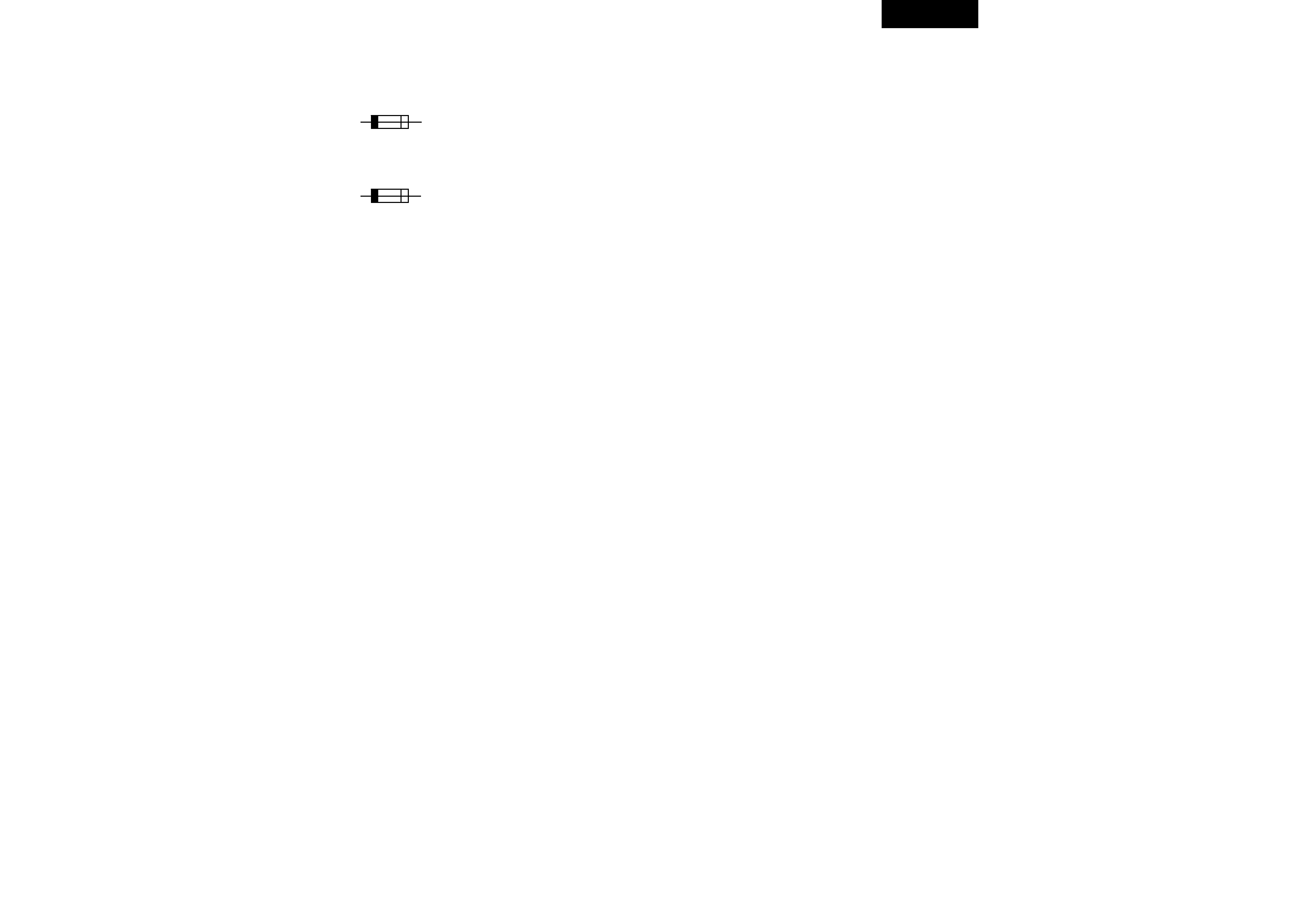
1. Replacing the fuse
This symbol located near the fuse
indicates that the fuse used is fast
operating type. For continued protection against fire hazard,
replace with same type fuse. For fuse rating refer to the
marking adjacent to the symbol.
Ce symbol indique le fusible utlise est a rapide.
Pour une protection permanente, n'untiliser que fusibles de
meme type. Ce darnier est la qu le present symbol est appse.
Circuit No. Part No.
Description
F901
252159 2A-UL/T-237 <D>
NOTE: <D>: 120 V model only
2. Safety check out
(Only U. S. A. model)
After correcting the original service problem, perform the
following safety check before releasing the set to the customer.
Connect the insulating-resistance tester between the plug of
power supply cord and screw on the back panel.
Specifications: 3.3M ohm +/- 10% at 500 V.
3. To initialize the unit
1. Press the standby button.
2. Press and hold down the STANDBY/ON, them press the
LATE NIGHT butoon at remoter controller.
3. After "CLEAR" is dislpayed, and initialized the unit.
4. Test mode
1. Press the standby button.
2. Press and hold down the STANDBY/ON, them press the
CHANNEL butoon.
3. Press the LEVEL/DISTANCE button and get the test mode
displayed "TEST-1-00".
EX) "TEST-1-00~01" is used the fan control operation.
GXW-5.1
background image
GXW-5.1
15G
14G
12G
10G
7G
1G
13G
S2
S1
11G
9G
8G
6G
5G
4G
3G
2G
a
b
j
k
c
n
p
r
h
g
m
d
(15G - 1G)
e
f
­­­­
­­­­
­­­­
­­­­
P2
­­­­
­­­­
­­­­
­­­­
­­­­
P3
­­­­
S2
­­­­
­­­­
­­­­
S1
­­­­
P4
a
a
a
a
a
a
a
a
a
a
a
a
a
a
a
P5
h
h
h
h
h
h
h
h
h
h
h
h
h
h
h
P6
j
j
j
j
j
j
j
j
j
j
j
j
j
j
j
P7
k
k
k
k
k
k
k
k
k
k
k
k
k
k
k
P8
b
b
b
b
b
b
b
b
b
b
b
b
b
b
b
P9
f
f
f
f
f
f
f
f
f
f
f
f
f
f
f
P10
m
m
m
m
m
m
m
m
m
m
m
m
m
m
m
P11
g
g
g
g
g
g
g
g
g
g
g
g
g
g
g
P12
c
c
c
c
c
c
c
c
c
c
c
c
c
c
c
P13
e
e
e
e
e
e
e
e
e
e
e
e
e
e
e
P14
r
r
r
r
r
r
r
r
r
r
r
r
r
r
r
P15
p
p
p
p
p
p
p
p
p
p
p
p
p
p
p
P16
n
n
n
n
n
n
n
n
n
n
n
n
n
n
n
P17
d
d
d
d
d
d
d
d
d
d
d
d
d
d
d
15G
14G
13G
12G
11G
10G
9G
8G
7G
6G
5G
4G
3G
2G
1G
P1
(15-BT-80GNK)
FL TUBE VIEW
background image
GXW-5.1
1G
2G
3G
4G
5G
6G
7G
8G
9G
10G
11G
13G
14G
15G
P1
P2
P3
P4
P5
100
99
98
97
96
95
94
93
92
91
90
89
88
87
86
85
84
83
82
81
Vdd
18
0
P6
STBY/RECV
27
9
VFL
Not
used
37
8
P7
Not
used
47
7
P8
Not
used
57
6
P9
Not
used
67
5
P10
SDO
77
4
P11
SCK
87
3
P12
Not
used
97
2
P13
RESET
10
71
P14
X2
11
70
P15
X1
12
69
P16
GND
13
68
P17
XT2
14
67
Not
used
GND
15
66
+5V
16
65
GAINCTL
VOLSLT
17
64
Not
used
18
63
POWER
~DSPRST
19
62
Not
used
~DSPCS
20
61
ENC2
Not
used
21
60
ENC1
DSPSCK
22
59
Not
used
DSPSDO
23
58
FS96
DSPSDI
24
57
ERF
GND
25
56
Not
used
26
55
Not
used
Not
used
27
54
Not
used
MODE
28
53
BTA15
Not
used
29
52
BTA16
Not
used
30
51
BTA17
32
33
34
35
36
37
38
39
40
41
42
43
44
46
47
48
49
50
THERM_IN
Not used
K0
+ 5
V
+ 5
V
SYSIN
~POFF
Not used
~REMIN
GND
Not used
AMUT
~ABOOT/~INT
Not used
Not used
+5V
Not used
~CODECPD
~DIRPD
31
45
DIRCS
FAN
HL
FAN
CTL
12G
LEVEL
IN
uPD780204GF-091-3BA
Q7001
V load
Power switch
Volume
U7001
GP1U281X
Q707
MX27C2000
EPROM
BTA17
BTA16
BTA15
Q801
AK4527
96kHz
CODEC
Q704
CS492604
DSP
AB/INT
96FS
DSPRST
Q701
AK4112A
96kHz 24bit
DIR
DIRPD
CODECPD
DSPCS
DIRCS
DSPSCK
DSPSOO
SDPSOI
ERF1
Q301
TC9482N
Electro volume
DATA
CK
Q503
TDA85630
Power IC
Power
Audio mute
From power muting circuit
STB
Q305
Q326
Gain
control
Q510
Fan control
MICROPROCESSOR CONNECTION DIAGRAM
FL
tube
X7001
5MHz

Reviews

There are no reviews of this manual yet.