ONKYO FR155 Service Manual

Cover page of ONKYO FR155 Service Manual

Service Manual for ONKYO FR155, downloadable as a PDF file.

Manual details

  • Immediate download after payment.
  • Delivered as a PDF file.
  • The manual has 48 pages
  • File size: 6.95 MB
  • Available language versions: English
  • Different language versions may vary sligthly in file size and page count.

We guarantee that...

  • our manuals are complete,
  • the manual includes circuit diagrams,
  • our manuals are checked with antivirus,
  • We'll issue refund if the manual is damaged, incomplete or unreadable (our refund policy)

Sample pages

Thumbnail of page 1Thumbnail of page 2Thumbnail of page 3Thumbnail of page 4
Thumbnail of page 5Thumbnail of page 6Thumbnail of page 7Thumbnail of page 8
Thumbnail of page 9
background image
FR-155
Ref. No. 3662
MODEL FR-155
092000
CD/MD TUNER AMPLIFIER
Silver model
UDT
120V AC, 60Hz
UGT
220 -230V AC, 50/60Hz
SAFETY-RELATED COMPONENT WARNING!!
COMPONENTS IDENTIFIED BY MARK
ON THE
SCHEMATIC DIAGRAM AND IN THE PARTS LIST ARE
CRITICAL FOR RISK OF FIRE AND ELECTRIC SHOCK.
REPLACE THESE COMPONENTS WITH ONKYO
PARTS WHOSE PART NUMBERS APPEAR AS SHOWN
IN THIS MANUAL.
MAKE LEAKAGE-CURRENT OR RESISTANCE
MEASUREMENTS TO DETERMINE THAT EXPOSED
PARTS ARE ACCEPTABLY INSULATED FROM THE
SUPPLY CIRCUIT BEFORE RETURNING THE
APPLIANCE TO THE CUSTOMER.
TABLE OF CONTENTS
Specifications -----------------------------------------------------------
Caution on replacement of optical pickup ---------------------------
Protection of eyes from laser beam during servicing ---------------
Laser Warning Label----------------------------------------------------
Service procedures -----------------------------------------------------
Front panel view --------------------------------------------------------
Connecting to Other Components------------------------------------
Remote controller -------------------------------------------------------
Setting the day of the Week and the Time----------------------------
IC Block diagram and descriptions -----------------------------------
Microprocessor Connection Diagram---------------------------------
Microprocessor Terminal Description--------------------------------
Operation of the Microprocessor--------------------------------------
MD Mechanism Exploded view-------------------------------------
MD Mechanism Disassembly ----------------------------------------
MD Mechanism Reassembly ----------------------------------------
MD Adjustment Procedures ------------------------------------------
MD Mount View / Messages--------------------------------------------
CD Mechanism Exploded View ---------------------------------------
CD Adjustment Procdedure-------------------------------------------
Clock Adjustment Procdedure-----------------------------------------
Handling of Pickup-----------------------------------------------------
Chassis Exploded View Parts List------------------------------------
Chassis Exploded View ------------------------------------------------
Block Diagram----------------------------------------------------------
Block Diagram (Power Supply Section)------------------------------
Schematic Diagram (Amplifire Section)-----------------------------
Printed Circuit Board View 1------------------------------------------
Schematic Diagram (CD&Microprocessor Section)----------------
Printed Circuit Board View 2------------------------------------------
Schematic Diagram (Power Supply Section)-----------------------
Printed Circuit Board View 3------------------------------------------
Printed Circuit Board View Parts List--------------------------------
Wiring View-------------------------------------------------------------
Packing View Parts List------------------------------------------------
2
2
3
3
3
4
5
6
6
7
15
16
17
18~19
20,21
22
23~25
26
27,28
29
30
31
32
33
35
37
39
41
43
45
47
49
51~54
55
57
background image
FR-155
SPECIFICATIONS
2
General
Power supply
AC 220-230 V, 50/60 Hz
AC 120 V, 60 Hz
Power consumption
63 W (220-230 V, 50/60 Hz)
82 W (120 V, 60 Hz)
(Standby)
7 W
(Energy Save)
1.5 W
Clock precision
monthly error:
30 seconds
(at 25 degrees Celsius)
Dimensions (W
× H × D)
205
× 154 × 356 mm
8-1/16"
× 6-1/16" × 14"
Weight
5.5 kg, 12.1 lbs
Amplifier
Power output
2
× 26 W at 4 WEIAJ
2
× 21 W at 6 WEIAJ
Rated Power
2
× 19 W min, RMS at 4 W
1 kHz no more than
0.2 % THD
Dynamic power
2
× 23 W at 4 W
Total harmonic distortion
0.4 % at rated power
IM distortion
0.2 % at rated power
Damping factor
25 at 8
Sensitivity and impedance
LINE, TAPE:
150 mV, 50 kW
CDR: 150 mV, 50 kW
Frequency response
10 to 50,000 Hz : +0dB / -3 dB
Tone Control
S.BASS1: +4 dB at 40 Hz
S.BASS2: +8 dB at 50 Hz
S.BASS3: +4 dB at 10 kHz/
+8 dB at 50 Hz
Signal to noise ratio
LINE, CDR, TAPE: 100dB
(IHF-A)
Muting
50 dB
CD player
Signal readout system
Optical non-contact
Frequency response
10 Hz to 20 kHz ( 3 dB)
Wow and flutter
Below threshold of
measurability
MD recorder
Signal readout system
Optical non-contact
Recording time
320 minutes maximum
(at LP4 mode)
Frequency response
10 Hz to 20 kHz ( 3 dB)
Wow and flutter
Below threshold of
measurability
Tuner
Tuning range
FM: 87.50 to 108.00 MHz
(50 kHz steps)
AM: 522 to 1611 kHz
(9 kHz steps)
Usable sensitivity
FM Mono:11.2 dBf,
1.0
µV (75 WIHF)
Stereo:17.2 dBf,
2.0
µV (75 WIHF)
AM: 30
µV
50 dB quieting sensitivity
FM Mono:17.2 dBf,
2.0
µV (75 W)
Stereo:37.2 dBf,
20.0
µV (75 W)
Capture ratio
2.0 dB
Image rejection ratio
FM: 85 dB
AM: 40 dB
IF rejection ratio
FM: 90 dB
AM: 40 dB
Signal to noise ratio
FM Mono : 73 dB IHF
Stereo : 67 dB IHF
AM: 40 dB
Selectivity
FM: 50 dB
( 300 kHz at 40 kHz devi.)
Harmonic distortion
FM: Mono: 0.7 %
Stereo: 0.3 %
AM: 0.7 %
Frequency response
FM: 30 to 15,000 Hz ( 1.5 dB)
Stereo separation
FM: 40 dB at 1,000 Hz
FM: 30 dB at 100 to 10,000 Hz
Specifications and features are subject to change without noitce.
CAUTION ON REPLACEMENT OF OPTICAL PICKUP
The laser diode in the optical pickup block is so sensitive to
static electricity, surge current and etc., that the components
are liable to be broken down or its reliability remarkably
deteriorated.
During repair,carefully take the following precautions.
(The following precautions are included in the service
parts.)
PRECAUTIONS
1.Ground for the work-desk.
Place a conductive sheet such as a sheet of copper
(with impedance lower than 10 Mohm) on the work-
desk and place the set on the conductive sheet so that
the chassis can be grounded.
2.Grounding for the test equipments and tools.
Test equipments and toolings should be grounded in
order that their ground level is the same the ground of
the power source.
3. Grounding for the human body.
Be sure to put on a wrist-strap for grounding whose
other end is grounded.
Be particularly careful when the workers wear
synthetic fiber clothes, or air is dry.
4. Select a soldering iron that permits no leakage and
have the tip of the iron well-grounded.
5. Do not check the laser diode terminals with the
probe of a circuit tester or oscilloscope.
.
background image
FR-155
3
PROTECTION OF EYES FROM LASER BEAM DURING SERVICING
This set employs a laser. Therefore, be sure to follow carefully
the instructions below when servicing.
WARNING!!
SERVICE WARNING : DO NOT APPROACH THE
LASER EXIT WITH THE EYE TOO CLOSELY.
IN CASE IT IS NECESSARY TO CONFIRM LASER
BEAM EMISSION, BE SURE TO OBSERVE FROM
A DISTANCE OF MORE THAN 30cm FROM THE
SURFACE OF THE OBJECTIVE LENS ON THE
OPTICAL PICK-UP BLOCK.
Laser Diode Properties
Material: GaAS/GaALAs
Wavelength: 780nm
Emission Duration: continuous
Laser output: max. 0.5mW*
*This output is the value measured at a distance about 1.8mm
from the objective lens surface on the Optical Pick-up Block.
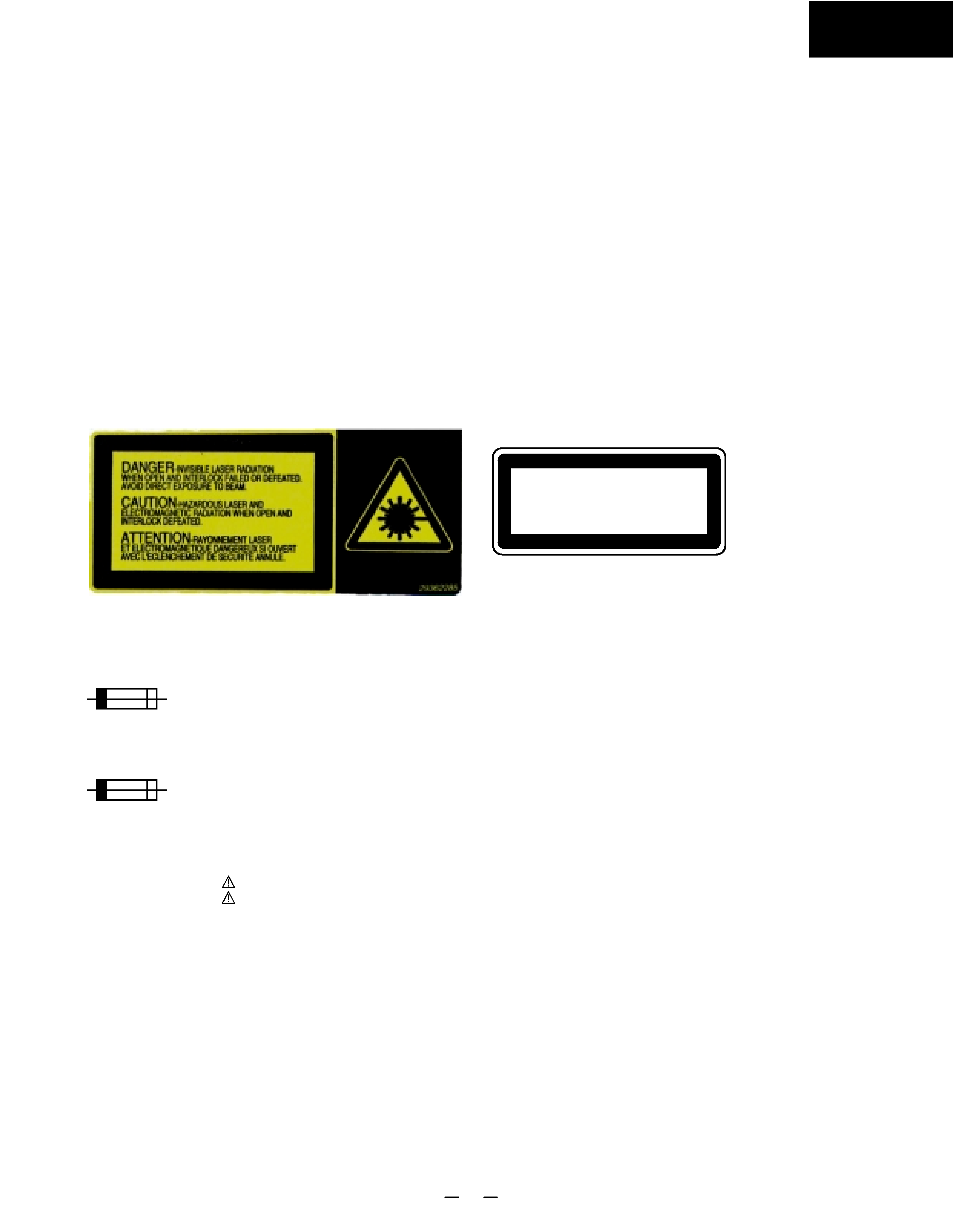
LASER WARNING LABEL
The label shown below are affixed.
1. Warning label
2. Class 1 label
"CLASS 1 LASER
PRODUCT"
LUOKAN 1
LASERLAITE
KLASS 1
LASER APPARAT
SERVICE PROCEDURE
1. Replacing the fuses
3. Safety-check out
(Only U.S.A. model)
After correcting the original service problem perform the
follwing safety check before releasing the set to the customer
Connect the insulating-resistance tester between the plug of
power supply cord and terminal GND on the back panel.
Specifications: More than 10Mohm at 500V
REF.NO.
PART NO.
DESCRIPTION
F901
252157
1.25A-UL/T-237, Fuse <DT>
252083
0.4A-SE-EAW, Fuse <GT>
NOTE :
<DT> : 120 V model only
<GT> : 220 V~230 V model only
This symbol located near the fuse indicates that the
fuse used is show operating type, For continued protection against
fire hazard, replace with same type fuse , For fuse rating, refer to
the marking adjest to the symbol.
Ce symbole indique que le fusible utilise est e lent.
Pour une protection permanente, n'utiliser que des fusibles de meme
type. Ce demier est indique la qu le present symbol est apposre.
1. Press and the hold down the CD STOP button , then press the
STANDBY/ON button.
2. After " All lighting " is displayed, the preset memory and each
mode stored in the memory, are initialized and will return to the
factory settings.
3. Press the STANDBY/ON button.
4. Unplug the AC plug from the wall outlet.
2. To initialize the unit
4. Memory Preservation
This unit does not require memory preservation batteries. A built-in
memory power back-up system preserves the contents of the
memory during power failures and even when the unit is un-plugged.
The unit must be plugged in order to charge the back-up
system.
The memory preservation period after the unit has been unplugged
varies depending on climate and placement of the unit. On the
average, memory contents are protected over a period of a few
weeks after the last time the unit has been unplugged. This period
is shorter when the unit is exposed to a highly humid climate.
5. Changing the AM band step
With the exception of the worldwide models, a tuning step selector
switch is not provided. When you change the band step, change
the parts as shown below.
To 10kHz
To 9kHz
R748
open
1 kohms
R749
1 koms
open
R748 and R749 on the microprocessor PC board (NADG-6933)
background image
FR-155
4
MD disc slot
Remote control sensor
CD disc tray
PHONES jack
STANDBY/ON button
REC MODE switch
CD DUBBING button
MD
REC button
MD
button
MD
button
MD
button
CD/MD button
VOLUME control
FM/AM button
OTHER INPUTS button
CD
button
CD
button
CD
button
DISPLAY button
EDIT/CLEAR/NO button
REPEAT/YES button
MULTI JOG dial
TIMER button
/
buttons
TUNING
/
buttons
MODE button
AUTO/MONO button
FRONT PANEL VIEW
ENERGY SAVE button
/indicator
SOURCE indicator
CD indicator
TIMER indicator
MD indicator
MD/CD setting indicators
Multi-purpose display
CH (channel) indicator
When lit, the indicators show
what the mulit-purpose display
( Multi-purpose display) above
them is currently displaying.
Indicators for radio frequency
information
TOC indicator
MD operation indicators
DUB indicator
CD operation indicators
Playback mode indicators
DIGITAL indicator
LEVEL-SYNC indicator
MUTING indicator
Recording level indicator
Timer indicators
DISPLAY
DISCRETE OUTPUT STAGE
WIDE RANGE AMPLIFIER
TECHNOLOGY
CD / MD TUNER AMPLIFIER
VOLUME
ACOUSTIC
PRESENCE
MIN
MAX
STANDBY / ON
DISC LOADING MECHANISM
FM /AM
OTHER
INPUTS
CD DUBBING
AUTO / MONO
PHONES
EDIT / CLEAR
DISPLAY
REPEAT
NO
YES
TUNING
TIMER
PUSH TO ENTER
MULTI JOG
MODE
CD / MD
REC
REC MODE
SP
ENERGY SAVE
MONO
LP2
LP4
SLEEP
ONCE
W.DAY
W.END
REC
SOURCE
CD
TIMER
MD
MD
CH
CD
MUTING LEVEL-SYNC DIGITAL
CHAIN
REPEAT
RANDOM
DISC TRACK ELAPSED REMAIN TITLE
TUNED
STEREO
AUTO
MONO
CD
MD
TOC
DUB
- 40 - 20
-10
0 OVER
- 6
- 2
-
L
R
1 TR MEMORY
ACOUSTIC PRESENCE
background image
FR-155
5
PRE OUT
SUB
WOOFER
Connecting a subwoofer
The FR-155 has a SUBWOOFER PRE OUT jack. Connect
an active subwoofer (a subwoofer that contains an amplifier),
or connect an amplifier to the FR-155, then connect a non-
active subwoofer to the amplifier.
Active subwoofer
(with a built-in amplifier)
Subwoofer
(without a built-in amplifier)
: Signal flow
Amplifier
Connecting a DVD player
In addition to the optical digital audio connections,you must also
make analog connections.To connect to the Onkyo DVD player, be
sure to connect to the LINE-1 jacks with the audio connection cable,
not the LINE-2 jacks.
Digital
audio
output
Analog
audio output
L
R
Audio connection
cable
Optical fiber
audio cable
: Signal flow
FR-155's rear panel
DVD player
OUT
IN
REMOTE
CONTROL
PR
DIGITAL
S
WO
OPTICAL
OUT
(REC)(PL
LINE-1
LINE-2
TAPE
L
R
white
red
Connecting an Onkyo stereo
cassette tape deck
The illustration below describes the connections to an Onkyo stereo
cassette tape deck. To connect to another cassette tape deck, connect the
TAPE OUT (REC) and IN (PLAY) jacks of the unit to the INPUT (REC) and
OUTPUT (PLAY) jacks of the cassette tape deck, respectively.
FR-155's rear panel
Audio
connection
cable
cable supplied with
the Onkyo stereo
cassette tape deck
: Signal flow
Onkyo stereo cassette
tape deck rear panel
OUT
IN
REMOTE
CONTROL
PRE OUT
DIGITAL
SUB
WOOFER
OPTICAL
OUT
IN
OUT
IN
(REC)(PLAY)(PLAY)
(REC)
LINE-1
LINE-2
TAPE
L
R
L
R
CDR
L
R
(REC)
(PLAY)
INPUT
OUTPUT
REMOTE
CONTROL
Audio connection
cable
white
red
Connecting an Onkyo compact
disc recorder
The following diagram shows how to connect an
optional Onky o compact disc recorder to the FR-155.
Connect its CDR OUT (REC) jac ks and IN (PLA Y)
jac ks to the disc recorderÕ
s INPUT (REC) jac ks and
OUTPUT (PLAY) jac ks respectively.
The
jack connection enables you to use the
following functions:
¥ You can control a connected Onky o compact disc
recorder from the FR-155' s remote controller.
¥ When the connected Onky o compact disc recorder
plays bac k, the Input Selector on the FR-155 is
automatically switched to CD-R.
¥ To connect both CD recorder and a cassette tape
deck to the FR-155, connect the
connectors of
both devices .
: Signal flow
Jacks on the compact disc
recorder's rear panel
FR-155's rear panel
red white
Audio connection cable
An
cable that comes
with the compact disc recorder
OUT
IN
REMOTE
CONTROL
PRE OUT
DIGITAL
SUB
WOOFER
OPTICAL
OUT
IN
OUT
IN
(REC)(PLAY)(PLAY)
(REC)
LINE-1
LINE-2
TAPE
L
R
L
R
CDR
OPTICAL
INPUT1
INPUT2
DIGITAL
OUTPUT
L
R
L
R
K
L
INPUT
(REC)
OUTPUT
(PLAY)
ANALOG
REMOTE
CONTROL
Optical fiber audio cable
Connecting a portable MD player
Refer to the portable MD playerÕs Instruction Manual.
Audio
connection
cable
: Signal flow
OUT
(REC
LINE-1
LINE-2
T
L
R
white
red
CONNECTING TO OTHER COMPONETS
SPEAKERS
CAUTION : SPEAKER IMPEDANCE
4 OHMS MIN. / SPEAKER
+
­
+
­
FM
75
OUT
IN
REMOTE
CONTROL
PRE OUT
DIGITAL
ANTENNA
SUB
WOOFER
OPTICAL
OUT
IN
OUT
IN
(REC)(PLAY)(PLAY)
(REC)
LINE-1
LINE-2
TAPE
L
R
L
R
L
R
CDR
AM
Rear Panel View

Reviews

There are no reviews of this manual yet.