ONKYO DV-S555 Service Manual

Cover page of ONKYO DV-S555 Service Manual

Service Manual for ONKYO DV-S555, downloadable as a PDF file.

We also have owner's manual to this model.

Manual details

  • Immediate download after payment.
  • Delivered as a PDF file.
  • The manual has 63 pages
  • File size: 4.18 MB
  • Available language versions: English
  • Different language versions may vary sligthly in file size and page count.

We guarantee that...

  • our manuals are complete,
  • the manual includes circuit diagrams,
  • our manuals are checked with antivirus,
  • We'll issue refund if the manual is damaged, incomplete or unreadable (our refund policy)

Sample pages

Thumbnail of page 1Thumbnail of page 2Thumbnail of page 3Thumbnail of page 4
Thumbnail of page 5Thumbnail of page 6Thumbnail of page 7Thumbnail of page 8
Thumbnail of page 9
background image
DV-S555
Ref. No.3685
SAFETY-RELATED COMPONENT
WARNING!!
COMPONENTS IDENTIFIED BY MARK
ON THE
SCHEMATIC DIAGRAM AND IN THE PARTS LIST ARE
CRITICAL FOR RISK OF FIRE AND ELECTRIC SHOCK.
REPLACE THESE COMPONENTS WITH ONKYO
PARTS WHOSE PART NUMBERS APPEAR AS SHOWN
IN THIS MANUAL.
MAKE LEAKAGE-CURRENT OR RESISTANCE
MEASUREMENTS TO DETERMINE THAT EXPOSED
PARTS ARE ACCEPTABLY INSULATED FROM THE
SUPPLY CIRCUIT BEFORE RETURNING THE
APPLIANCE TO THE CUSTOMER.
072001
BMDD
120V AC, 60Hz
BMUP, SMUP
230 -240V AC, 50/60Hz
BMUT, BMUS,
GMUT, GMUR
SERVICE MANUAL
SERVICE MANUAL
DVD Player
DV-S555
Black, Silver and Golden models
LAST M
COND. M
DIMMER
DISPLAY
STANDBY
ON
ANGLE
AUDIO
SUBTITLE
MENU
TOP MENU
SETUP
RETURN
STOP
PAUSE
FUNCTION M
OPEN/CLOSE
DOWN
UP
FR
FF
CLEAR
PROGRAM
RANDOM
REPEAT
A-B
STEP/SLOW
SEARCH
REMOTE CONTROLLER RC-
449DV
PLAY
23
456
78
9
1
0
+10
+
-
ENTER
TV
ON/STANDBY
VOL +
VOL -
TV/ VCR
CH +
CH -
TV
DVD
LAST M
COND. M
DIMMER
DISPLAY
STANDBY
ON
ANGLE
AUDIO
SUBTITLE
MENU
TOP MENU
SETUP
RETURN
STOP
PAUSE
FUNCTION M
OPEN/CLOSE
DOWN
UP
FR
FF
CLEAR
PROGRAM
RANDOM
REPEAT
A-B
STEP/SLOW
SEARCH
REMOTE CONTROLLER RC-
450DV
PLAY
23
456
78
9
1
0
+10
+
-
ENTER
TV
ON/STANDB
Y
VOL+
VOL-
TV/ VCR
CH+
CH-
TV
TV
DVD
DVD
U.S.A., Canadian
models only
Other models
100 - 240V AC, 50/60Hz
RC-449DV
RC-450DV
background image
DV-S555
Specifications and features are subject to change without notice.
Power supply
North American models:
AC 120 V, 60 Hz
Other models:
AC 100 - 240 V, 50/60 Hz
Power consumption
North American models:
14 W
Other models:
15 W
Weight
3.4 kg, 7.1 lbs.
External dimensions
435 x 91 x 312 mm (W/H/D), 17-1/8" x 3-9/16" x 12-5/16"
Signal system
PAL/NTSC
Regional restriction code
North American area:
1
Some Asian are:
3
South American area: 4
Chiness area:
6
Laser
Semiconductor laser , wavelength 650 nm
Frequency range (digital audio)
DVD linear sound:
48 kHz sampling 4 Hz to 22 kHz
96 kHz sampling 4 Hz to 44 kHz
Audio CD:
4 Hz to 20 kHz
Signal-to-noise ratio (digital audio)
More than 100 dB
Audio dynamic range (digital audio)
More than 96 dB
Harmonic distortion (digital audio)
Less than 0.05 %
Wow and flutter
Below measurable level (less than +/- 0.001 % (W.PEAK))
Operating conditions
Temperature: 5 C to 35 C (41 F to 95 F), Operation status: Horizontal
Video output
1.0 V (p-p), 75 ohm, negative sync., pin jack x 1
S-video output
(Y) 1.0 V (p-p), 75 ohm , negative sync., Mini DIN 4-pin x 1
(C) 0.286 V (p-p), 75 ohm
Component video output
(Y) 1.0 V (p-p), 75 ohm , negative sync., pin jack x 1
(P B)/(P R) 0.7 V (p-p), 75 ohm <MDD/MUS/MUT/MUR>
Audio output (digital output Optical)
Optical connecter x 1
Audio output (digital output Coaxial)
0.5 V (p-p), 75 ohm, pin jack x 1
Audio output (2-Channel Audio)
2.0 V (rms), 320 ohm , pin jack (L, R, MONO) x 1
DVD Player
Outputs
RGB signal output, 0.7 V (p-p), 75 ohm, SCAR T socket x 1 <MUP>
Audio output (analog audio)
2.0 V (rms), 470 ohm, pin jack (L, R. MONO) x 1
SPECIFICATIONS
background image
DV-S555
A
1
2
3
4
5
BCD
SERVICE NOTE
1. Replacing the fuses
2. Safety-check out
(Only U.S.A. model)
After correcting the original service problem perform the
following safety check before releasing the set to the customer
Connect the insulating-resistance tester between the plug of
power supply cord and terminal GND on the back panel.
Specifications: More than 10M ohm at 500V
REF.NO.
PART NO.
DESCRIPTION
F1
252152 or
1.6A-T/UL-ST2 or
252147
1.6A-TSC, Fuse <MDD>
NOTE :
<MDD> : 120 V model only
: 100 - 240 V model only
This symbol located near the fuse indicates that the
fuse used is show operating type, For continued protection against
fire hazard, replace with same type fuse , For fuse rating, refer to
the marking adjust to the symbol.
Ce symbole indique que le fusible utilise est e lent.
Pour une protection permanente, n'utiliser que des fusibles de meme
type. Ce demier est indique la qu le present symbol est apposre.
252273 or
1.6A-SE-TL250V or
252077
1.6A-SE-EAK Fuse
TO REDUCE THE RISK OF FIRE OR ELECTRIC SHOCK, DO NOT EXPOSE THIS APPLIANCE TO RAIN
OR MOISTURE. DANGEROUS HIGH VOLTAGES ARE PRESENT INSIDE THE ENCLOSURE. DO NOT OPEN THE
CABINET. REFER SERVICING TO QUALIFIED PERSONNEL ONLY.
TO PREVENT ELECTRIC SHOCK, MATCH WIDE BLADE OF PLUG TO WIDE SLOT, FULLY INSERT.
POUR EVITER LES CHOCS ELECTRIQUE, INTRODUIRE LA LAME LA PLUS LARGE DA LA FICHE DANS LA
BORNE CORRESPONDANTE DA LA PRISE ET POUSSER JUSQU' AU FOND.
WARNING :
CAUTION :
ATTENTION :
The lightning flash with arrowhead symbol, within an equilateral triangle, is
intended to alert the user to the presence of uninsulated "dangerous voltage"
within the product's enclosure that may be of sufficient magnitude to constitute
a risk of electric shock to persons.
The exclamation point within an equilateral triangle is intended to alert the user
to the presence of important operating and maintenance (servicing) instruction
in the literature accompanying the appliance.
<MUP,MUS,MUT,MUR>
<MUP,MUS,MUT,MUR>
1.Ground for the work-desk.
Place a conductive sheet such as a sheet of copper (with impedance lower than 10Mohm) on the work-desk and
place the set on the conductive sheet so that the chassis.
2.Grounding for the test equipments and tools.
Test equipments and toolings should be grounded in order that their ground level is the same the ground of the power source.
3. Grounding for the human body.
Be sure to put on a wrist-strap for grounding whose other end is grounded.
Be particularly careful when the workers wear synthetic fiber clothes, or air is dry.
4. Select a soldering iron that permits no leakage and have the tip of the iron well-grounded.
5. Do not check the laser diode terminals with the probe of a circuit tester or oscilloscope.
PRECAUTIONS
background image
DV-S555
16
17
18
6
8 9 10 11
12
13
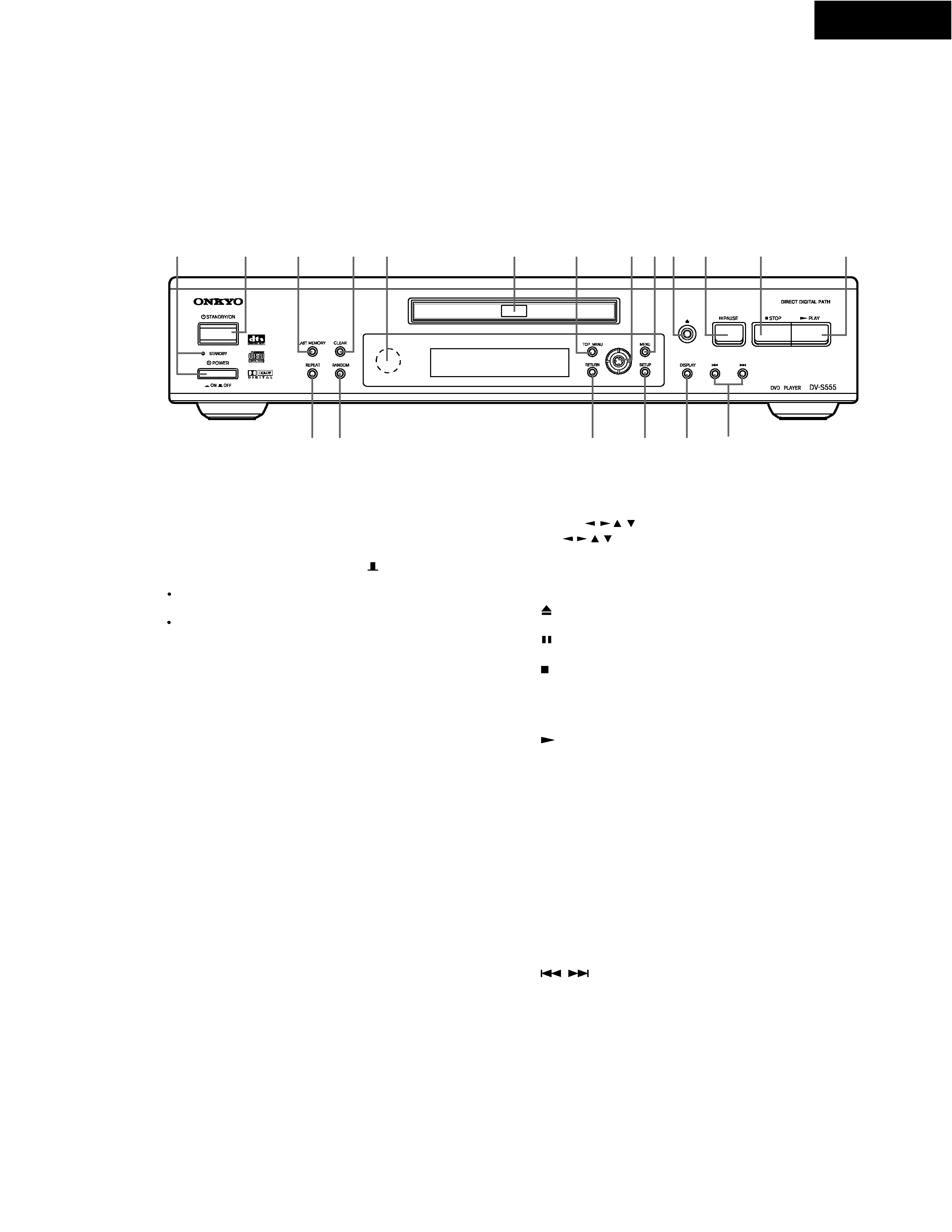
1. POWER switch and STANDBY indicator
Turns on the main power supply for the DV-S555. The DV-S555
enters standby state and the STANDBY indicator lights up.
Pressing the switch again to the off position (
OFF) shuts down
the main power supply into the DV-S555.
Before turning on the power, make sure all cables are properly
connected.
Turning on the DV-S555 may cause a momentary power
surge that might interfere with other electrical equipment on
the same circuit. If this is a problem, plug the DV-S555 into a
different electrical circuit.
2. STANDBY/ON button
When ST ANDBY/ON button is pressed to ON while the POWER
switch is set to ON, the DV-S555 turns on and the STANDBY
indicator turns off. Pressing the button again returns the DV-S555
to the standby state. This state turns of f the display , disables
control functions.
LAST MEMORY button
You can resume DVD or Video CD playback from the point you
last watched even if the disc is removed from the player. Press
LAST MEMORY during playback to set a Last Memory point.
When you want to resume playback of that disc, press LAST
MEMORY in the stop mode and playback starts from the
memorized point. Last Memory locations can be stored for up to 5
DVDs and 1 V ideo CD.
4. CLEAR button
Works in conjunction with a number of player functions. Use to
cancel repeat and random playback, and to edit programs.
5. Remote control sensor
Point the remote control toward the remote sensor to operate the
player .
Disc tray
When loading a disc, place discs in the disc tray with the label
side facing up.
TOP MENU button
Press to call up the top menu programmed on the DVD.
Depending on the DVD, the top menu may be identical to the
DVD menu.
8. Cursor ( / / / ) button/ENTER button
Use
to move through the options on menu screens and
to change settings. Use ENTER to implement settings selected
with the cursor buttons or to set items highlighted in a menu.
9. MENU button
Use to display or close the DVD menu or MP3 Navigator screen.
OPEN/CLOSE button
Press to open and close the disc tray.
PAUSE button
Press during playback to pause. Press again to resume playback.
STOP button
Press to stop playback. Pressing once enables playback to
resume from a point shortly before the location where it stopped.
Pressing twice causes the disc to return to the beginning of the
disc if playback starts again.
PLAY button
Press to start or resume playback.
14. REPEAT button
Use to set the repeat mode.
15. RANDOM button
Press to play chapters/tracks in random order.
RETURN button
Use to go one menu back (current settings are maintained). Use
RETURN when you do not want to change the option setting in a
menu.
SETUP button
Press when the player is in either play or stop mode to open and
close the Setup screen.
DISPLAY button
Press during playback to display statistical disc information.
Press repeatedly to display different information.
/
button
Press to go back or advance to previous chapters/tracks. Press
and hold to perform fast-reverse/fast-forward playback scanning.
3.
6.
7.
/ / /
(
)
10.
11.
12.
13.
16.
17.
18.
19.
1
2
3
4
5
14 15
7
19
PANELVIEW
Frontpanel
background image
DV-S555
PANEL VIEW
TITLE
CHAPTER TRACK
REMAIN
LAST
COND.
DTS
REPEAT
DVD
V C D
D
GUI
L
MONO
R
VIDEO
OUTPUT
Y
CB
CR
COMPONENT
OPTICAL COAXIAL
AC INLET
REMOTE
CONTROL
ANALOG
OUTPUT
DIGITAL
OUTPUT
VIDEO
S VIDEO
DV-S555
DVD PLAYER
/ indicator
Inserted disc indicator
TITLE indicator
4. Angle icon indicator
5. CHAPTER/TRACK indicator
REPEA T indicator
7. REMAIN indicator
LAST indicator
COND. indicator
D indicator
DTS indicator
GUI indicator
Multifunctional indicator
(e.g. operating status and error messages)
VIDEO OUT VIDEO jack
Connect to the video input on a TV or monitor or AV amplifier or
receiver with video input capability .
VIDEO OUT S-VIDEO OUT jack
If your TV or monitor has an S-video input, clear picture
reproduction is possible by connecting the player to your TV or
monitor via the S-Video jack.
You can switch between [S1] and [S2] S-video output from the
Setup menu.
VIDEO OUT COMPONENT jacks
If your TV or monitor has component video inputs, you can
produce a higher quality picture on your TV or monitor by
connecting to the component video outputs on this unit.
ANALOG OUTPUT jacks
Use to output two-channel audio (analog) to the audio stereo
inputs on a TV or stereo amplifier . If you are connecting to a
receiver that has both digital and analog input jacks for DVD
player connection, it may be beneficial to make both connections.
DIGITAL OUTPUT OPTICAL jack
Use to output the digital audio signal recorded on discs. You can
output the digital signal via the optical output jack to an AV
amplifier or receiver .
DIGITAL OUTPUT COAXIAL jack
Use to output the digital audio signal recorded on discs. You can
output the digital signal via the coaxial output jack to an AV
amplifier or receiver .
jack
Use to connect this player to another component bearing the
RI
mark. This lets you control this unit as though it were a
component in a system.
AC INLET
Use to connect the power cord to the wall outlet.
(North American models rear panel shown)
Display
1.
2.
3.
6.
8.
9.
10.
11.
12.
13.
1
2
3
4
5
6
7
8
9
10 11 12
13
Rear panel
1.
2.
3.
4.
5.
6.
7.
8.
1
2 3
4
5 6
7
8

Reviews

There are no reviews of this manual yet.