ONKYO DSR-7.3 Service Manual

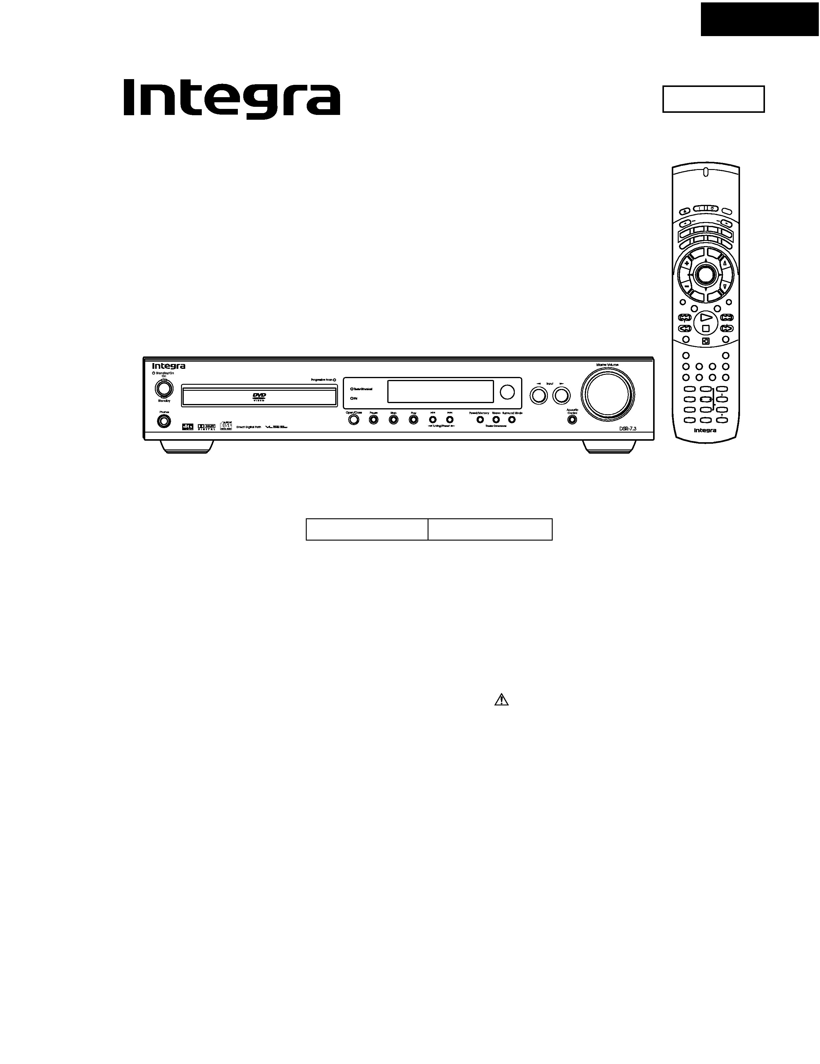
Cover page of ONKYO DSR-7.3 Service Manual

Service Manual for ONKYO DSR-7.3, downloadable as a PDF file.

We also have owner's manual to this model.

Manual details

  • Immediate download after payment.
  • Delivered as a PDF file.
  • The manual has 95 pages
  • File size: 8.89 MB
  • Available language versions: English
  • Different language versions may vary sligthly in file size and page count.

We guarantee that...

  • our manuals are complete,
  • the manual includes circuit diagrams,
  • our manuals are checked with antivirus,
  • We'll issue refund if the manual is damaged, incomplete or unreadable (our refund policy)

Sample pages

Thumbnail of page 1Thumbnail of page 2Thumbnail of page 3Thumbnail of page 4
Thumbnail of page 5Thumbnail of page 6Thumbnail of page 7Thumbnail of page 8
Thumbnail of page 9
background image
DSR-7.3
SERVICE MANUAL
SERVICE MANUAL
DVD RECEIVER
Black model
MODEL
DSR-7.3
120V AC, 60Hz
B UDD, B MDD
Ref. No. 3745
Sep, 2002
RC-507M
Se nd
On
Sta nd b y
Op
en/
Clos
e
2
T-D Setup
IPM
SW Mode
Distance
T-D/ ST
A-B
Surround
A.Control
-- / ---
Mo d e
Enter
Repeat
Muting
Up/ Down
SP Setup
Test Tone
CH Sel
RC-
507M
Audio
Last M
Prog ra m
Random
Late Night
Timer
Angle
Clear
Subtitle
FM Mode
Inp ut Se lec to r
Light
TV
Disp lay
VOL
ENTER
C H
TV In
p u
t
Se tu
p
DV
D
Re c vr
Ta p e
Tun
Step/ Slow
To
p M
enu
Men
u
Retu
rn
Clo
c k
Sle
ep
Dim m
er
123
456
+10
Search
0
789
SAFETY-RELATED COMPONENT
WARNING!!
COMPONENTS IDENTIFIED BY MARK
ON THE
SCHEMATIC DIAGRAM AND IN THE PARTS LIST ARE
CRITICAL FOR RISK OF FIRE AND ELECTRIC SHOCK.
REPLACE THESE COMPONENTS WITH ONKYO
PARTS WHOSE PART NUMBERS APPEAR AS SHOWN
IN THIS MANUAL.
MAKE LEAKAGE-CURRENT OR RESISTANCE
MEASUREMENTS TO DETERMINE THAT EXPOSED
PARTS ARE ACCEPTABLY INSULATED FROM THE
SUPPLY CIRCUIT BEFORE RETURNING THE
APPLIANCE TO THE CUSTOMER.
background image
DSR-7.3
NU
NU
SYSOUT
TPRT
VPRT
HPIN
NU
NU
PRL
SELSDO
SELSCLK
SELMUT
VSS1
SPACS
SPAFR
POWERL
AMUT
TUMUT
SD
STEREO
1
2
3
4
5
6
7
8
9
10
11
12
13
14
15
16
17
18
19
20
TRAYIN
MODE3
MODE4
AVSS
NU
DVDPOWER
AVREF1
NU
NU
XRESET
XSI
XSO
XSCLK
XREADY
MCRDY/FPHS
MCSD/FPSI
MCSDO/FLSO
MCCLK/FPCLK
MCRST
SYSIN
21
22
23
24
25
26
27
28
29
30
31
32
33
34
35
36
37
38
39
40
I/O
PIN NAME
NO.
DESCRIPTION
ACTIVE
I
I
I
-
I
O
-
O
O
O
I
O
O
I
I
O
O
O
O
I
O
O
O
I
I
I
O
O
O
O
O
O
-
O
O
O
O
O
I
I
A/D
A/D
A/D
-
H
H
-
-
-
H
H
H
CLK
H
H
H
H
CLK
L
H
-
-
L
L
H
H
H
H
H
H
CLK
H
H
H
H
H
H
H
L
L
MICROPROCESSOR TERMINAL DESCRIPTION-1
Q8001: MPD784225GC-XXX-8BT
Input pin of detected signal of tray state.
Input pin of initial setting.
Ground pin of A/D converter.
No used (Connect to ground)
No used.
Output pin of control signal for power supply of DVD main circuit.
Input pin of reference voltage or D/A converter.
No used.
No used.
Output pin of reset signal to microprocessor in DVD main board.
Output pin of serial data from microprocessor in DVD main board.
Output pin of serial data to microprocessor in DVD main board.
Output pin of clock signal to microprocessor in DVD main board.
Output pin of communication for microprocessor in DVD main board.
Input pin of ready data from Sub-microprocessor.
Input pin of data from sub-microprocessor.
Output pin of data to sub-microprocessor.
Output pin of serial clock to sub-microprocessor.
Output pin of reset signal for Sub-microprocessor.
Input pin of RI (system control signal).
No used.
No used.
Output pin RI (System control).
Input pin of signal from thermal detection circuit.
Input pin of DC voltage detection signal from power amplifier.
Input pin of detection signal from insert state of headphone plug.
No used.
No used.
No used.
Output pin of serial data latch for BD3811 (volume and selector control IC).
Output pin of serial data clock for BD3811 (volume and selector control IC).
Output pin of muting signal for BD3811 (volume and selector control IC).
Ground pin.
Output pin of control signal for center speaker relay and surround speaker relay drive.
Output pin of control signal for front speaker relay drive.
Output spin of control signal for main power relay drive.
Output pin of control signal for audio muting circuit.
Output pin of control signal for of tuner muting circuit.
Input signal of detection signal of receiving state of broadcast.
Input pin of detection signal of FM stereo pilot signal.
background image
DSR-7.3
MICROPROCESSOR TERMINAL DESCRIPTION-2
Q8001: MPD784225GC-XXX-8BT
PLLSDO
PLLCLK
PLLCE
NU
NU
DIRCS
DSPSDI
DIRINT1
DIRINT0
INTREQ/ABOOT
DSPCS
ROM/RAM
ADDR15
ADDR16
ADDR17
DSPCLK
DSPSDO
DSPRST
DIRPD
RESET
POFF
RDSCLK
RDSDATA
RDSSIG
XLT
IRIN2
VSS0
VDD1
X2
X1
TEST
XT2
XT1
VDD0
AVDD
BAND
DVDBAND
IPM
MODE1
MODE2
61
62
63
64
65
66
67
68
69
70
71
72
73
74
75
76
77
78
79
80
41
42
43
44
45
46
47
48
49
50
51
52
53
54
55
56
57
58
59
60
I/O
PIN NAME
NO.
DESCRIPTION
ACTIVE
O
O
O
-
-
O
I
I
I
I/O
O
O
O
O
O
O
O
O
O
-
H
CLK
H
-
-
L
H
H
H
H
L
H/L
H
H
H
H
H
L
L
-
Output pin of serial data for PLL IC of tuner unit.
Output pin of serial clock for PLL IC of tuner unit.
Output pin of serial latch for PLL IC of tuner unit.
No used.
No used.
Output pin of chip select signal to AK4586.
Input pin of serial data from CS493292 and AK4586.
Input pin of detection signal from function status of AK4586.
Input pin of interrupt request detection signal from function status of AK4586.
Input/output pin of signal from interrupt request and auto boot of CS493292
Output pin of signal for chip select.
Output pin of signal for select ROM or RAM.
Output pin of signal for select of DSP boot ROM address 15
Output pin of signal for select of DSP boot ROM address 16
Output pin of signal for select of DSP boot ROM address 17
Output pin of serial clock to CS493292 and AK4586.
Output pin of serial data to CS493292 and AK4586.
Output pin of reset signal to CS493292.
Output pin of power down signal to AK4586.
Input pin for system reset.
I
I
I
I
I
I
-
-
-
-
-
-
-
-
-
I
I
I
I
I
L
CLK
H
H
H
L
-
-
-
-
-
-
-
-
-
A/D
A/D
A/D
A/D
A/D
Input pin of power failure detected signal.
No used by DSR-7.3.
No used by DSR-7.3.
No used by DSR-7.3.
Input pin of latch signal from DVD main microprocessor.
Input pin of external control signal.
Ground pin.
Power supply pin.
Connect to ceramic oscillator.
No used.
No used. (open)
No used. (open)
Power supply pin.
Power supply pin for A/D converter.
Input pin for initial setting of destination (tuner band).
Input pin for initial setting of destination (DVD region cord).
Input pin for IPM (intelligent power management) function.
Input pin of initial setting.
background image
DSR-7.3
SPECIFICATIONS
AMPLIFIER SECTION
Power Output (FTC)
All channels 25 watts per channel min.
RMS. into 6 ohms two channel driven,
1,000 Hz with no more than 10% total
harmonic distortion.
Continuous power output (DIN)
All channels 21 watts per channel min.
RMS. into 6 ohms two channel driven,
1,000 Hz
Continuous Power output (EIAJ)
All channel 26 watts per channel min.
RMS. into 6 ohms two channel driven,
1,000 Hz
Total Harmonic Distortion 10 % at rated power
0.2 % at 1 watt output
IM Distortion
10 % at rated power
0.2 % at 1 watt output
TUNER SECTION
Tuning Range
FM: 87.50 to 108.00 MHz (50 kHz steps)
AM: 530 to 1710 kHz (10 kHz steps)
Usable Sensitivity
FM: Mono
11.2 dBf, 1.0 µV (75 ohms IHF)
0.9 µV (75 ohms DIN)
Stereo
17.2 dBf, 2.0 µV (75 ohms IHF)
23 µV (75 ohms DIN)
AM: 30 µV
50 dB Quieting Sensitivity
FM: Mono
17.2 dBf, 2.0 µV (75 ohms)
Stereo
37.2 dBf, 20.0 µV (75 ohms)
Capture Ratio
FM: 2.0 dB
Image Rejection Ratio
FM: 40 dB
AM: 40 dB
IF Rejection Ratio
FM: 90 dB
DVD SECTION
Signal readout system
Optical non-contact
Linear velocity
3.49 m/s (Single Layer)
3.84 m/s (Dual Layer)
Error correction system
Reed Solomon Product Code
Signal system
Standard NTSC
Regional restriction code South American area: 4
Output Level and Impedance
Composite
1.0Vp-p, 75 ohms
S-Video
Y: 1.0 Vp-p, 75 ohms
C: 0.286 Vp-p, 75 ohms
Component
Y: 1.0 Vp-p, 75 ohms
PB, PR: 0.7 p-p, 75 ohms
Laser
Semiconductor laser, wavelength 650 nm
Frequency response
10 Hz to 44 kHz (96 kHz)
Signal-to-noise ratio (digital audio)
More than 100 dB
Audio dynamic range (digital audio)
More than 93 dB
Harmonic distortion (digital audio)
Less than 0.025%
Wow and flutter
Below threshold of measurability
Operating conditions
Temperature: 5 C to 35 C (41 F to 95 F),
Operation status: Horizontal
GENERAL
AC 120 V, 60 Hz
Power Consumption
: 130 W
Power Consumption (standby mode)
: 2.0 W
: 29 W (*)
(*) when clock display is on
Specifications and features are subject to change without notice.
Damping Factor
40 at 8 ohms
Input Sensitivity and Impedance
DIGITAL OPTICAL IN
­21 to ­15 dBm
LINE (TV/LINE, MD/CDR/TAPE)
200 mV/50 kohms
Output Level and Impedance
DIGITAL OPTICAL OUT
­21 to ­15 dBm
REC OUT (MD/CDR/TAPE)
200 mV, 2.2 kohms
PRE OUT (SUBWOOFER)
1 V, 470 ohms
Frequency Response
20 to 30,000 Hz : +/­ 0.8 dB
Acoustic Control
1: +9 dB at 82 Hz
2: +9 dB at 82 Hz
+6 dB at 10,000 Hz
Signal-to-noise Ratio
100 dB (0.5 V INPUT LINE)
Muting
­50 dB
Dimensions (W x H x D)
Weight
AM: 40 dB
Signal-to-noise Ratio
FM: Mono
73 dB, IHF
Stereo
67 dB, IHF
AM: 40 dB
Alternate Channel Att. (+/­ 400 kHz) FM: Mono
55 dB, IHF
Selectivity
FM: 50 dB, DIN 55dB, IHF
AM Suppression Ratio
FM: 50 dB
Harmonic Distortion
FM: Mono
0.2 %
Stereo
0.3 %
AM:
0.7 %
Frequency response
FM: 30 to 15,000 Hz (+/­ 1.0 dB)
Stereo Separation
FM: 45 dB at 1,000 Hz
30 dB at 100 to 10,000 Hz
Stereo Threshold
FM: 17.2 dBf,
20 µV (75 ohms)
Output
FM: 500 mV
AM: 150 mV
Power Supply
435
81 366 mm (171/8
33/16
14 7/16 ins.)
7.0 kg (15.4 lb.)
background image
DSR-7.3
1
3
6
16
5
9
2
4
8
7
17
18
10
15
14
13
12
11
19
16
17
18
15
14
13
19
1
3
6
5
9
2
4
8
7
10
12
11
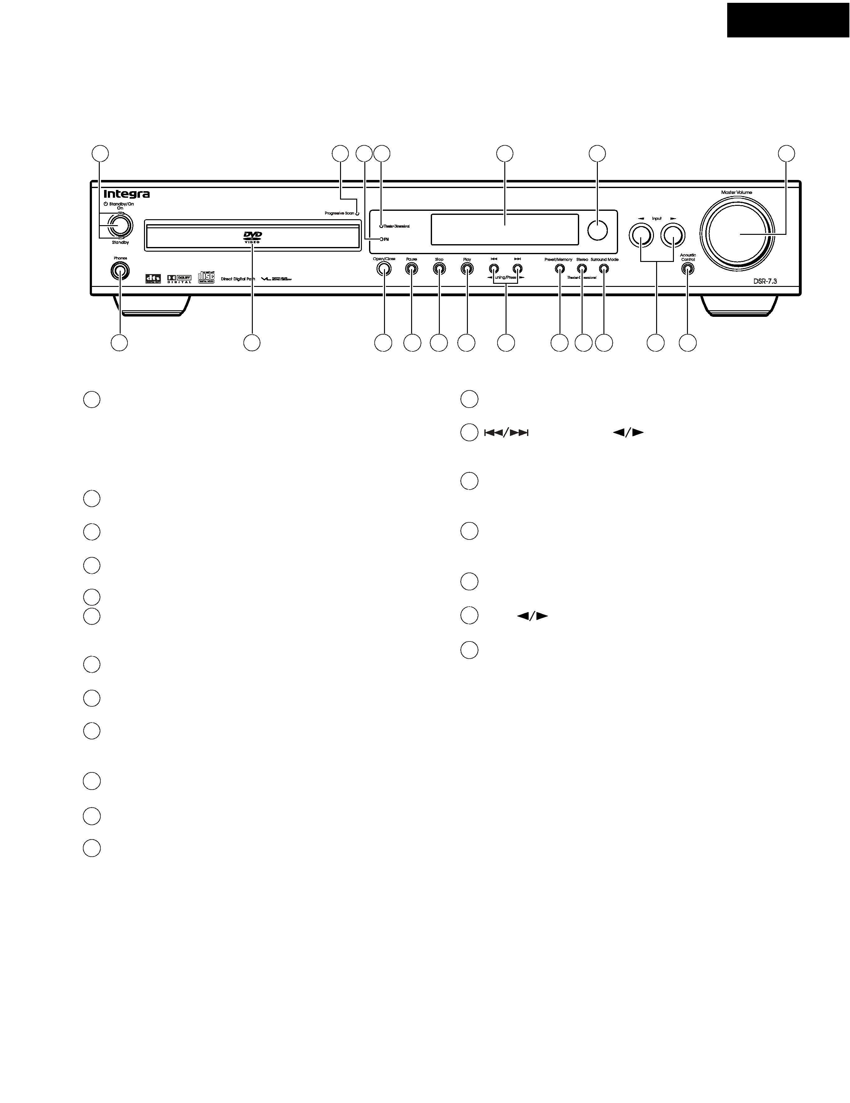
Standby/On button, On, Standby indicators
When Standby/On button is pressed to On, the DVD Receiver turns
on. The Standby indicator turns off, and the On indicator and the
display lights up. Pressing the button again returns the DVD
Receiver to the standby state. This state turns off the display,
disables control functions.
Progressive Scan indicator
Lights up when the DVD Receiver is set to progressive-scan video.
IPM (Intelligent Power Management) indicator
Lights up when the IPM function is active.
Theater-Dimensional indicator
Lights up while in the Theater-Dimensional mode.
Display
Remote control sensor
Point the remote control toward the remote sensor to operate the
DVD Receiver.
Master Volume control
The Master Volume dial is used to control the volume level.
Phones jack
This is a standard stereo jack for connecting stereo headphones.
Disc tray
When loading a disc, place discs in the disc tray with the label side
facing up.
Open/Close button
Press to open and close the disc tray.
Pause button
Press to pause playback. Press again to resume playback.
Stop button
Press to stop playback. Pressing once enables playback to resume
from a point shortly before the location where it was stopped.
Pressing twice causes the disc to return to the beginning of the
disc when playback starts again.
Play button
Press to start or resume playback.
,Tuning/Preset
buttons
Press to go back to previous or advance to next chapters/tracks.
Also, use these buttons to change the tuner frequency.
Preset Memory button
Press to assign the radio station that is currently tuned in to a
preset channel or delete a previously preset station.
Stereo/Theater-Dimensional button
Press to switch the listening mode between "STEREO" and
"THEATER-DIMENSIONAL".
Surround Mode button
Press to select a surround mode.
Input
buttons
Press to select an input source other than DVD.
Acoustic Control button and indicator
Press to change the acoustic mode to boost super bass/high
frequency sounds. When acoustic control mode is on the
"A.CTRL 1 or 2 h indicator lights.
PANEL VIEWS-1
FRONT PANEL

Reviews

There are no reviews of this manual yet.