ONKYO CR-315DAB Service Manual

Cover page of ONKYO CR-315DAB Service Manual

Service Manual for ONKYO CR-315DAB, downloadable as a PDF file.

Manual details

  • Immediate download after payment.
  • Delivered as a PDF file.
  • The manual has 67 pages
  • File size: 4.11 MB
  • Available language versions: English
  • Different language versions may vary sligthly in file size and page count.

We guarantee that...

  • our manuals are complete,
  • the manual includes circuit diagrams,
  • our manuals are checked with antivirus,
  • We'll issue refund if the manual is damaged, incomplete or unreadable (our refund policy)

Sample pages

Thumbnail of page 1Thumbnail of page 2Thumbnail of page 3Thumbnail of page 4
Thumbnail of page 5Thumbnail of page 6Thumbnail of page 7Thumbnail of page 8
Thumbnail of page 9
background image
CR-315/315DAB
SERVICE MANUAL
SERVICE MANUAL
RC-660S
CD RECEIVER
CR-315 for CS-315 Black and Silver models
MODEL
CR-315
MODEL
CR-315DAB
230V AC, 50Hz
120V AC, 60Hz
B MPP, S MPP
S MDC
Ref. No. 3963
082006
CR-315DAB for CS-315UK Silver model
CR-315 Silver model
S MPB
230V AC, 50Hz
220 - 230V AC, 50/60Hz
120V AC, 60Hz
S MGT, S MGQ
S MDT
SAFETY-RELATED COMPONENT
WARNING!!
COMPONENTS IDENTIFIED BY MARK
ON THE
SCHEMATIC DIAGRAM AND IN THE PARTS LIST ARE
CRITICAL FOR RISK OF FIRE AND ELECTRIC SHOCK.
REPLACE THESE COMPONENTS WITH ONKYO
PARTS WHOSE PART NUMBERS APPEAR AS SHOWN
IN THIS MANUAL.
MAKE LEAKAGE-CURRENT OR RESISTANCE
MEASUREMENTS TO DETERMINE THAT EXPOSED
PARTS ARE ACCEPTABLY INSULATED FROM THE
SUPPLY CIRCUIT BEFORE RETURNING THE
APPLIANCE TO THE CUSTOMER.
background image
CR-315/315DAB
SERVICE PROCEDURE-1
PROTECTION OF EYES FROM LASER BEAM DURING SERVICING
This set employs a laser. Therefore, be sure to follow carefully
the instructions below when servicing.
WARNING!!
SERVICE WARNING : DO NOT APPROACH THE
LASER EXIT WITH THE EYE TOO CLOSELY.
IN CASE IT IS NECESSARY TO CONFIRM LASER
BEAM EMISSION, BE SURE TO OBSERVE FROM
A DISTANCE OF MORE THAN 30cm FROM THE
SURFACE OF THE OBJECTIVE LENS ON THE
OPTICAL PICK-UP BLOCK.
Laser Diode Properties
Material: GaAS/GaALAs
Wavelength: 780nm
Laser output: max. 0.5mW*
Emission Duration: continuous
*This output is the value measured at a distance about 1.8mm
from the objective lens surface on the Optical Pick-up Block.
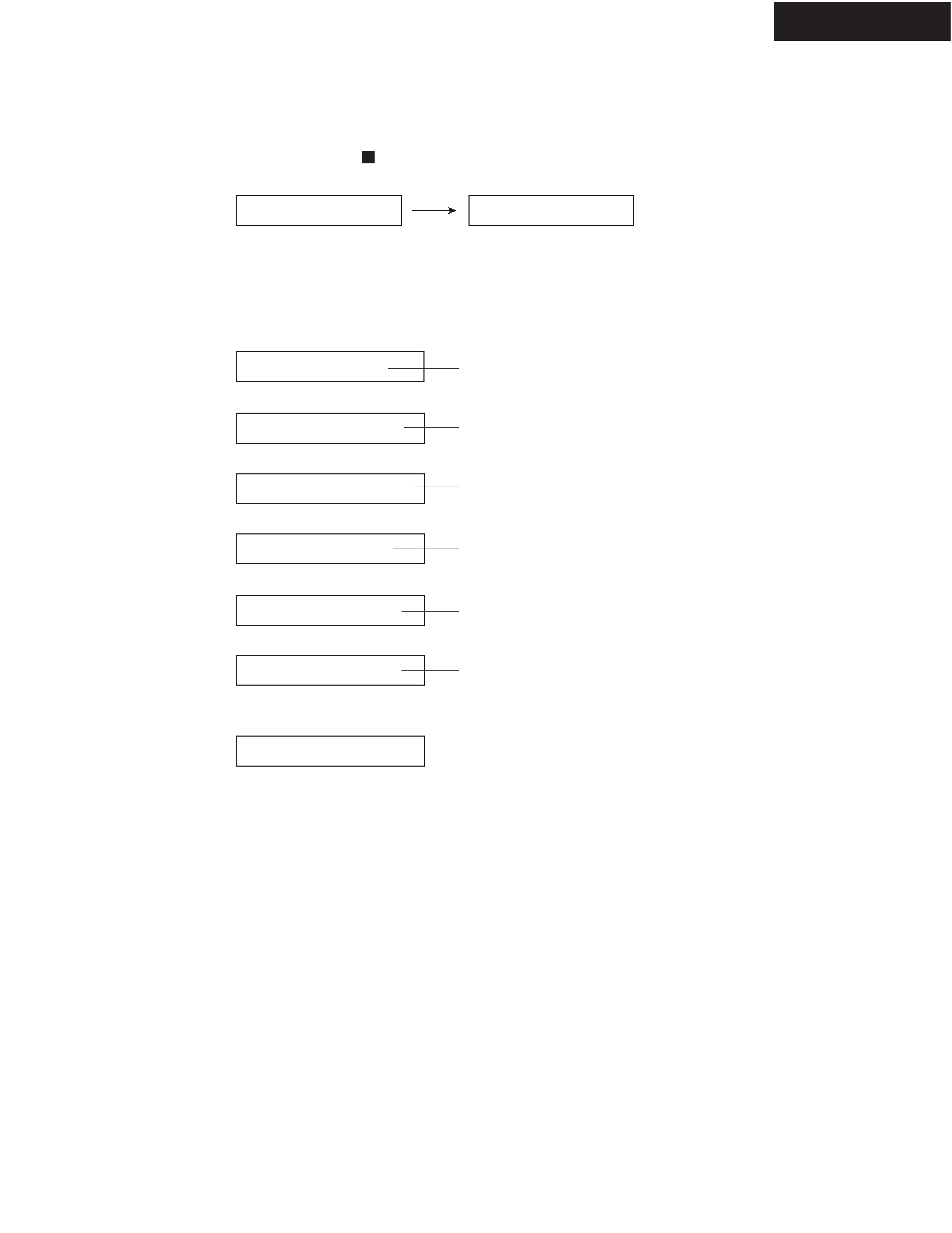
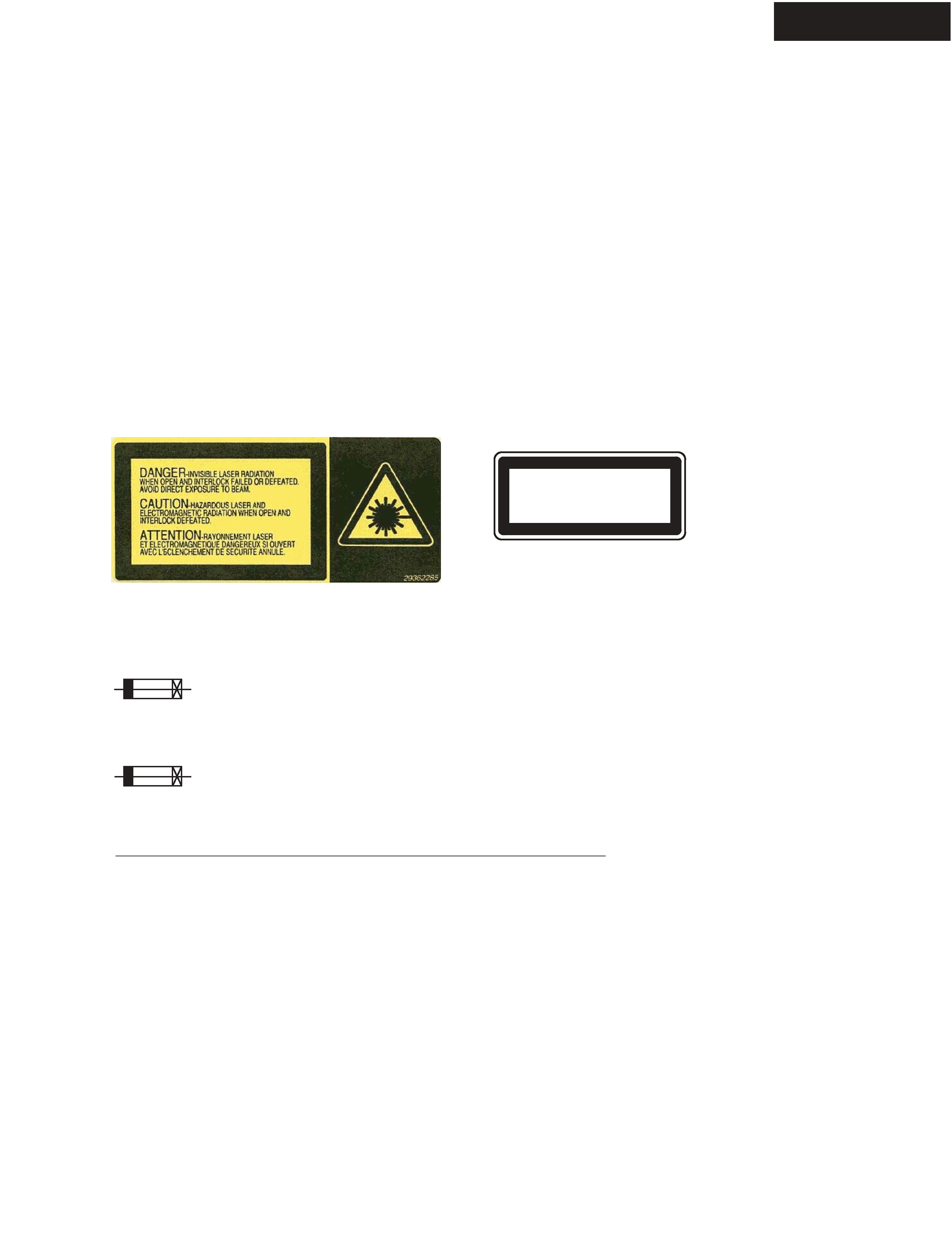
LASER WARNING LABEL
The label shown below are affixed.
1. Warning label
2. Class 1 label
"CLASS 1 LASER
PRODUCT"
LUOKAN 1
LASERLAITE
KLASS 1
LASER APPARAT
SERVICE PROCEDURE
1. Replacing the fuses
This symbol located near the fuse indicates that the
fuse used is show operating type, For continued protection against
fire hazard, replace with same type fuse , For fuse rating, refer to
the marking adjest to the symbol.
Ce symbole indique que le fusible utilise est e lent.
Pour une protection permanente, n'utiliser que des fusibles de meme
type. Ce demier est indique la qu le present symbol est apposre.
REF.NO.
F901
F901
F901
F901
F901
F901
PART NAME
FUSE
FUSE
FUSE
FUSE
FUSE
FUSE
DESCRIPTION
0.5A-SE-EAWK
1.25A-T/UL-ST2
0.5A-SE-EAWK
1.25A-T/UL-ST2
0.5A-SE-EAWK
0.5A-SE-EAWK
PART NO
252063GR
252251GR
252063GR
252251GR
252063GR
252063GR
<Notes>
<MPP> : CR-315 European model
<MDC> : CR-315 Canadian model
<MGT> : CR-315 Asian model
<MDT>: CR-315 Taiwanese model
<MGQ> : CR-315 Hong kong model
<DAB MPB> : CR-315DAB British model
REMARK
!, <MPP>
!, <MDC>
!, <MGT>
!, <MDT>
!, <MGQ>
!, <DAB MPB>
background image
CR-315/315DAB
SERVICE PROCEDURE-2
Clear
SYS :1.05
FL Display
Main:06628a
Serv:05805a
Sub :03506a
CR315 EU R
CheckSum:E338
FL Display
<EX.>
2. Initialize the unit
(1) Press and the hold down the STOP
button, then press the STANDBY/ON button at power on state.
Preset memory and each mode stored in the memory, are initialized and will return to the factory settings.
(2) Disconnect the AC power cord from a wall outlet.
3. Check version of microprocessor.
Main microprocessor (Q709), Servo microprocessor (Q101), Sub microprocessor (Q801).
(1) Press and the hold down the DISPLAY button, then press the STANDBY/ON button at power on state.
(2) Press the INPUT button.
(3) Press the INPUT button.
(4) Press the INPUT button.
(5) Press the INPUT button.
(6) Press the INPUT button.
(7) Press the STANDBY/ON button.
(8) Disconnect the AC power cord from a wall outlet.
Standby
Main microprocessor version
Standby
Sub microprocessor version
Servo microprocessor version
Release version
Check sum
Model & Destination
background image
CR-315/315DAB
CR-315/315DAB
EXPLODED VIEW
A303
x 9 pcs.
A004
x 9 pcs.
A217
x 2 pcs.
A112
x 4 pcs.
A117
x 3 pcs.
A121
x 2 pcs.
A103
x 14 pcs.
A111
x 2 pcs.
A105
x 3 pcs.
A123
x 4 pcs.
A309
x 2 pcs.
A102
x 6 pcs.
A104
A121
x 2 pcs.
A119
x 2 pcs.
A104
x 2 pcs.
A007
x 2 pcs.
U05
U10
U11
U04
P1002
P1102
E002
A009
A125
A132
x 4 pcs.
A305
A101
A109
A501
A127
A134
A128
U02
U01
U08
U06
T901
F901
P1101
P1001
P1003
U07
A301
A001
A213
A201
A205
A218
A302
A130
A106
A107
A108
A207
A115
x 4 pcs.
A113
Q559
Q560
Q557
Q558
A308
A306
A202
x 4 pcs.
U09
A110
x 2 pcs.
Refer to "EXPLODED VIEWS
OF MECHANISM"
background image
CR-315/315DAB
EXPLODED VIEWS OF MECHANISM-1
CD MECHANISM : DLM1A01-14CA / KSM-213CLCM
Z005
Z006
Z007
x 4 pcs.
Z009 (gold)
x 2 pcs.
Z010
x 4 pcs.
Z008 (silver)
x 2 pcs.
PARTS LIST
PART NO. (SN)
PART NAME
24800056
24800017
24818058
24820071
24820072
801632
Tray loading unit : DLM1A01-14CA
Refer to "EXPLODED VIEWS OF MECHANISM-2"
Drive unit : KSM-213CLCM
Refer to "EXPLODED VIEWS OF MECHANISM-3"
Q'TY
Front side
CD Tray Loading unit
CD Drive unit
INSULATOR
SPRING
SPRING
SCREW
DLM1A01-14CA
KSM-213CLCM
(CDC-A)
TP-D (silver)
TP-E (gold)
2.6 x 8 x W10
1
1
4
2
2
4
DESCRIPTION
<Note>
CD MECHANISM =
Tray loading unit : "DLM1A01-14CA"
+ Drive unit : "KSM-213CLCM"
REF. NO.
Z005
Z006
Z007
Z008
Z009
Z010

Reviews

There are no reviews of this manual yet.