1
CR-305X
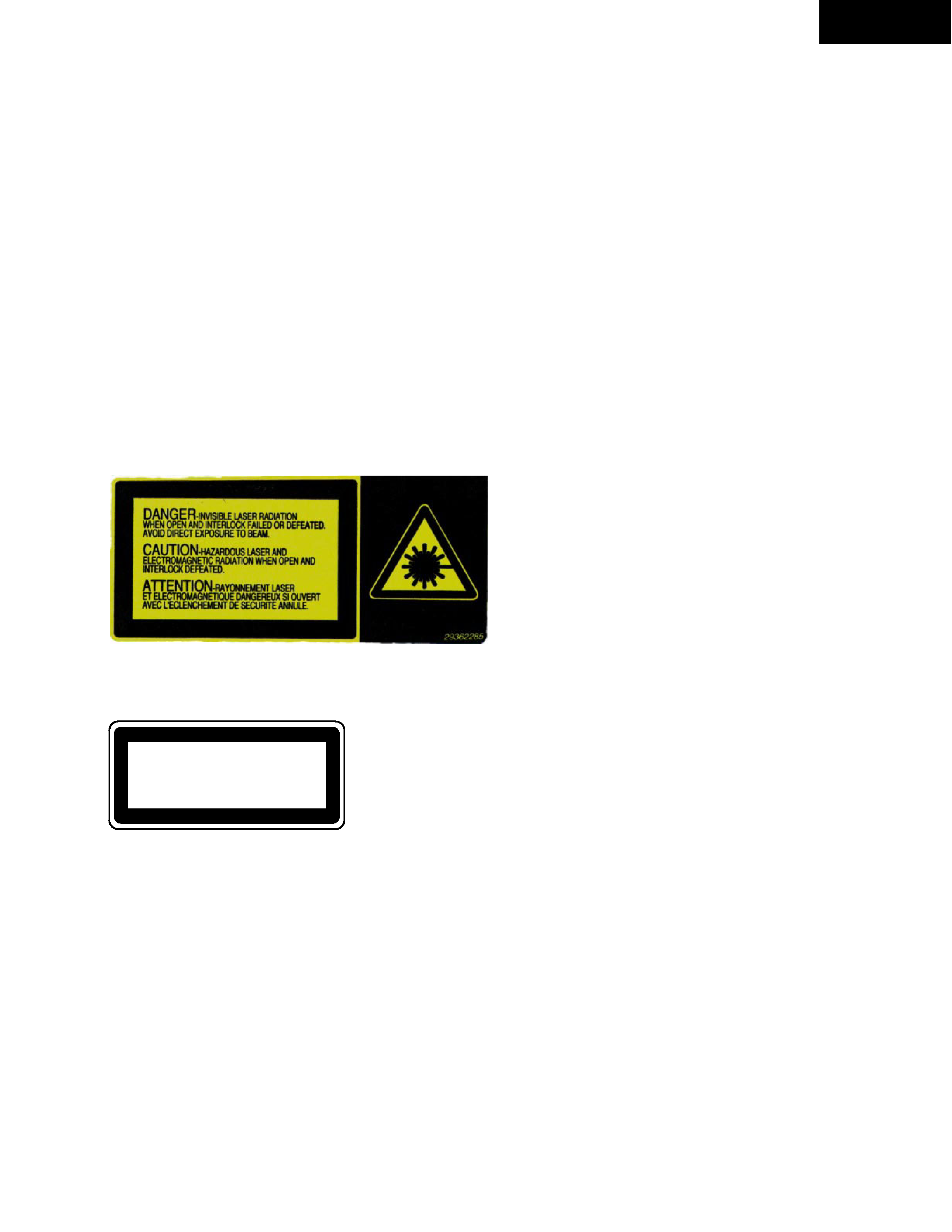
CAUTION ON REPLACEMENT OF OPTICAL PICKUP
The laser diode in the optical pickup block is so sensitive to
static electricity, surge current and etc., that the components
are liable to be broken down or its reliability remarkably
deteriorated.
During repair,carefully take the following precautions.
(The following precautions are included in the service
parts.)
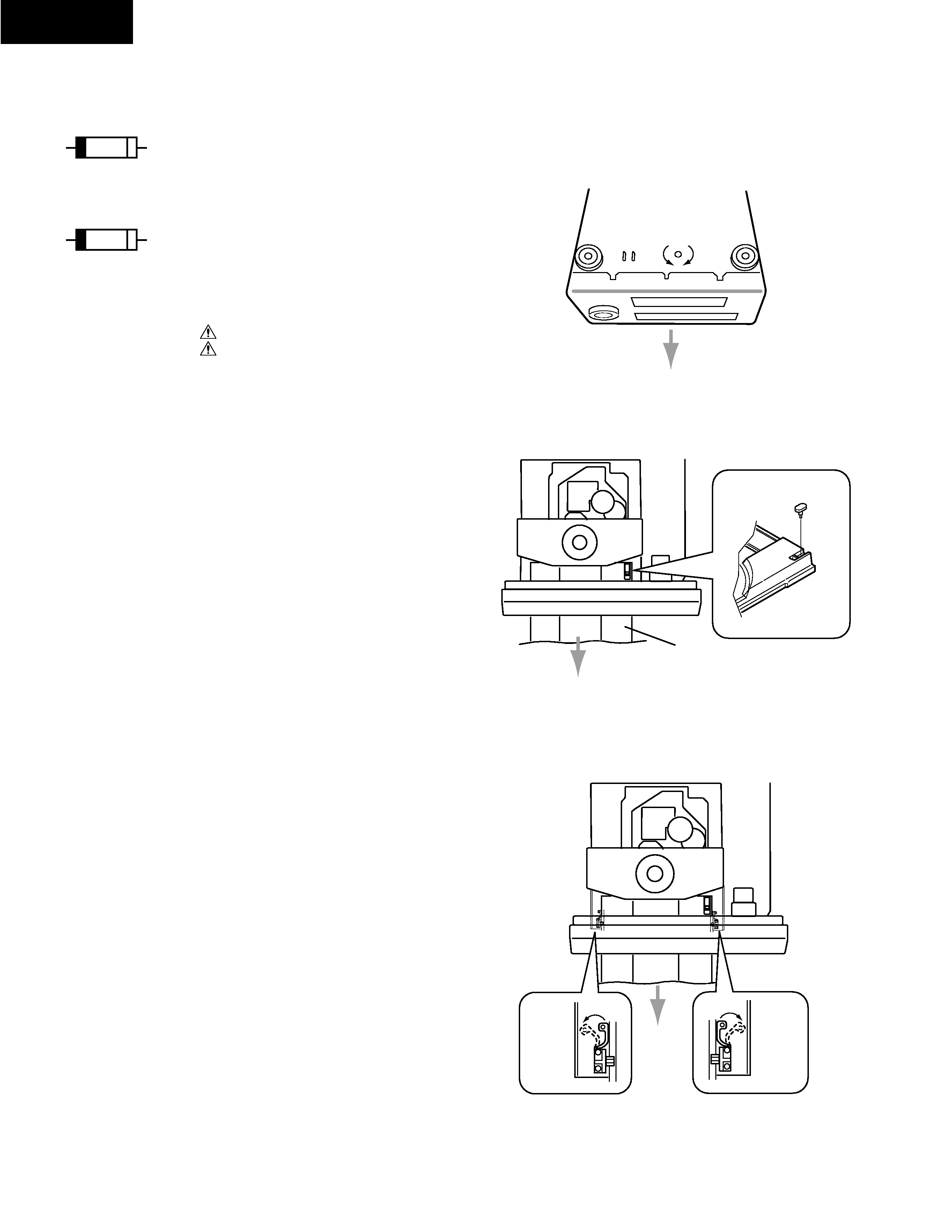
PRECAUTIONS
1.Ground for the work-desk.
Place a conductive sheet such as a sheet of copper
(with impedance lower than 10Mohm) on the work-
desk and place the set on the conductive sheet so that
the chassis can be grounded.
2.Grounding for the test equipments and tools.
Test equipments and toolings should be grounded in
order that their ground level is the same the ground of
the power source.
3. Grounding for the human body.
Be sure to put on a wrist-strap for grounding whose
other end is grounded.
Be particularly careful when the workers wear
synthetic fiber clothes, or air is dry.
4. Select a soldering iron that permits no leakage and
have the tip of the iron well-grounded.
5. Do not check the laser diode terminals with the
probe of a circuit tester or oscilloscope.
SPECIFICATIONS
AMPLIFIER
Po
w
er Output:
2 x 20 watts at 4 ohms 1 kHz DIN
2 x 17 watts at 6 ohms 1 kHz DIN
2 x 15 watts at 8 ohms 1 kHz DIN
2 x 20 watts min, RMS at 4 ohms 1 kHz
no more than 1 % THD (FTC rating)
2 x 25 watts at 4 ohms EIAJ
Dynamic Power:
2 x 24 watts at 4 ohms
2 x 18 watts at 8 ohms
Total Harmonic Distortion: 0.2 % at 10 watts output
IM Distortion:
0.2 % at 10 watts output
Damping Factor:
25 at 8 ohms
Sensitivity and Impedance: TAPE/CDR/MD IN : 150 mV, 50 kohms
Frequency Response:
10 to 50,000 Hz : +0 / 3 dB
Acoustic Presence:
1 40 Hz +6.0 dB
2 80 Hz +7.5 dB
3 40 Hz +10 dB
80 Hz +8.0 dB
4 40 Hz +10 dB
80 Hz +8.0 dB
10 kHz +4.5 dB
SingletoNoise Ratio:
100 dB (IHF A)
Muting
55 dB
CD PLAYER
Signal Readout System:
Optical noncontact
Reading Rotation:
About 500 200 r.p.m.
(constant linear velocity)
Linear Velocity:
1.2 1.4 m / s
Error Correction System:
Cross Interleave Reed Solomon code
D / A Converter:
1 bit
Digital Filter:
352.8 kHz 8 times over sampling
Number of Channels:
2 (stereo)
Frequency Response:
5 Hz 20 kHz
TUNER
Tuning range
FM: 87.9 to 107.9 MHz (200 kHz steps)
(U.S. & Canadian models)
87.5 to 108.00 MHz (50 kHz steps)
(Other area models)
AM: 530 to 1710 kHz (10 kHz steps)
(U.S. & Canadian models)
522 to 1611 kHz (9 kHz steps)
(Other area models)
Usable sensitivity
FM: Mono 11.2 dBf,
1.0 µV (75 ohms IHF)
0.9 µV (75 ohms DIN)
Stereo 17.2 dBf,
2.0 µV (75 ohms IHF)
23.0 µV (75 ohms DIN)
AM:
30 µV
50 dB Quieting sensitivity
FM: Mono 17.2 dBf, 2.0 µV (75 ohms)
Stereo 37.2 dBf, 20.0 µV (75 ohms)
Capture ratio
FM: 2.0 dB
Image rejection ratio
FM: 40 dB (U.S. & Canadian models)
85 dB (Other area models)
AM: 40 dB
IF rejection ratio
FM: 90 dB
AM: 40 dB
Signal to noise ratio
FM: Mono 73 dB, IHF
Stereo 67 dB, IHF
AM: 40 dB
Selectivity
FM: 50 dB DIN
(±300 kHz at 40 kHz Devi.)
AM Suppression Ratio: 50 dB
Harmonic distortion
FM: Mono 0.2%
Stereo 0.3%
AM: 0.7 %
Frequency response
FM: 30 to 15,000 Hz (±1.5 dB)
Stereo separation
FM: 35 dB at 1,000 Hz
25 dB at 100 to 10,000 Hz
Stereo threshold
FM: 17.2 dBf, 2.0 µV (75 ohms)
GENERAL
Power Supply:
AC 120 V, 60 Hz (U.S. & Canadian models)
(Some Asian models)
AC 230 V, 50 Hz (European models)
AC 220-230 V, 50/60 Hz (Other area models)
Power Consumption: 60 W (U.S. & Canadian models)
(Some Asian models)
55 W (Other area models)
Dimensions:
205 W x 103 H x 362 D mm
(8-1/6" x 4-1/16" x 14-1/4")
Weight:
4.0 kg (8.8 lbs)
Specifications and features are subject to change without notice
.
Power supply and voltage vary depending on the area in which the unit is purchased.