NAKAMICHI SOUNDSPACE9 Service Manual

Cover page of NAKAMICHI SOUNDSPACE9 Service Manual

Service Manual for NAKAMICHI SOUNDSPACE9, downloadable as a PDF file.

Manual details

  • Immediate download after payment.
  • Delivered as a PDF file.
  • The manual has 55 pages
  • File size: 1.9 MB
  • Available language versions: English
  • Different language versions may vary sligthly in file size and page count.

We guarantee that...

  • our manuals are complete,
  • the manual includes circuit diagrams,
  • our manuals are checked with antivirus,
  • We'll issue refund if the manual is damaged, incomplete or unreadable (our refund policy)

Sample pages

Thumbnail of page 1Thumbnail of page 2Thumbnail of page 3Thumbnail of page 4
Thumbnail of page 5Thumbnail of page 6Thumbnail of page 7Thumbnail of page 8
Thumbnail of page 9
background image
SS-9 General
i
Service Manual
Service Manual
Stereo Music System
SoundSpace 9
ST
Preset
FM
AM
Disc
Track
Remaining Time
Memory No.
Memory
Repeat
Random
Loud.
Vol.
background image
SS-9 General
i
Service Manual
Service Manual
Stereo Music System
SoundSpace 9
ST
Preset
FM
AM
Disc
Track
Remaining Time
Memory No.
Memory
Repeat
Random
Loud.
Vol.
background image
SS-9 General
ii
1.1. Product Code
D210
Abbreviations for Destinations:
CAN -- Canada
CH
-- China
DA
-- South America
EP
-- Europe
HK
-- Hong Kong
JPN
-- Japan
KR
-- Korea
OTR -- Other
TW
-- Taiwan
UK
-- United Kingdom
USA -- U.S.A.
AUS -- Australia
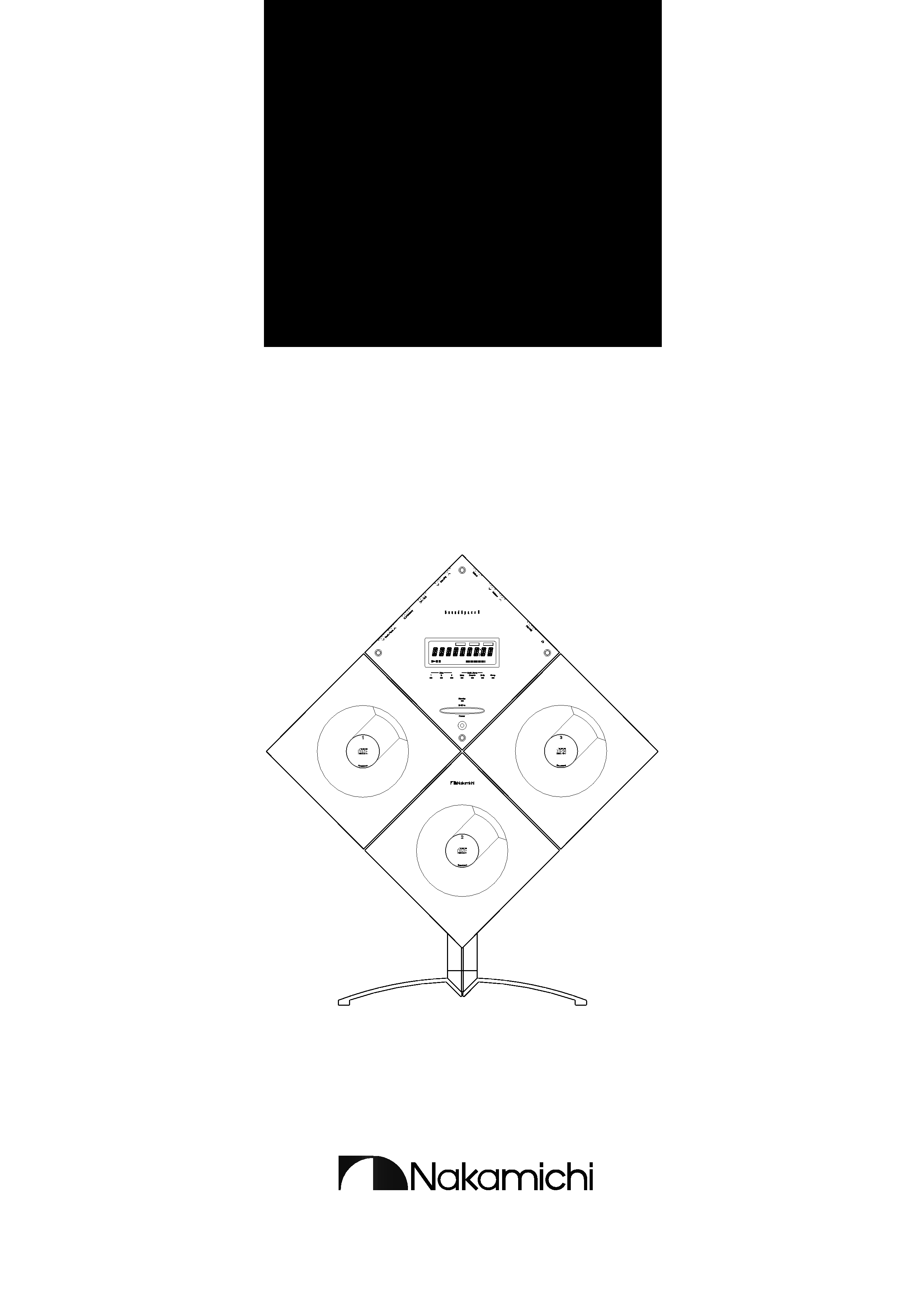
1.2. System Configuration
The SoundSpace consists of the following units.
q Main Unit (See pages 1-1, 1-2, ... in this manual)
Controls entire of the System. Mainly consists of the
following sections:
· Control section (including the system control mi-
croprocessor)
· Tuner section
· Operation panel control section
· CD player section (including the mechanism con-
trol microprocessor)-- 3 identical CD player sec-
tions (Interchangeable with each other except for
the Door Cap Ass'y on which the disc number is
written.)
q Subwoofer
(See pages 2-1, 2-2, ... in this manual)
· Subwoofer
· Power amp. section
· Power supply section
q Satellite Speakers L/R
(See pages 3-1, 3-2, ... in this manual)
q Main Remote Control/Sub Remote Control
GENERAL
Fig. 1.1 SS-9 System Configuration
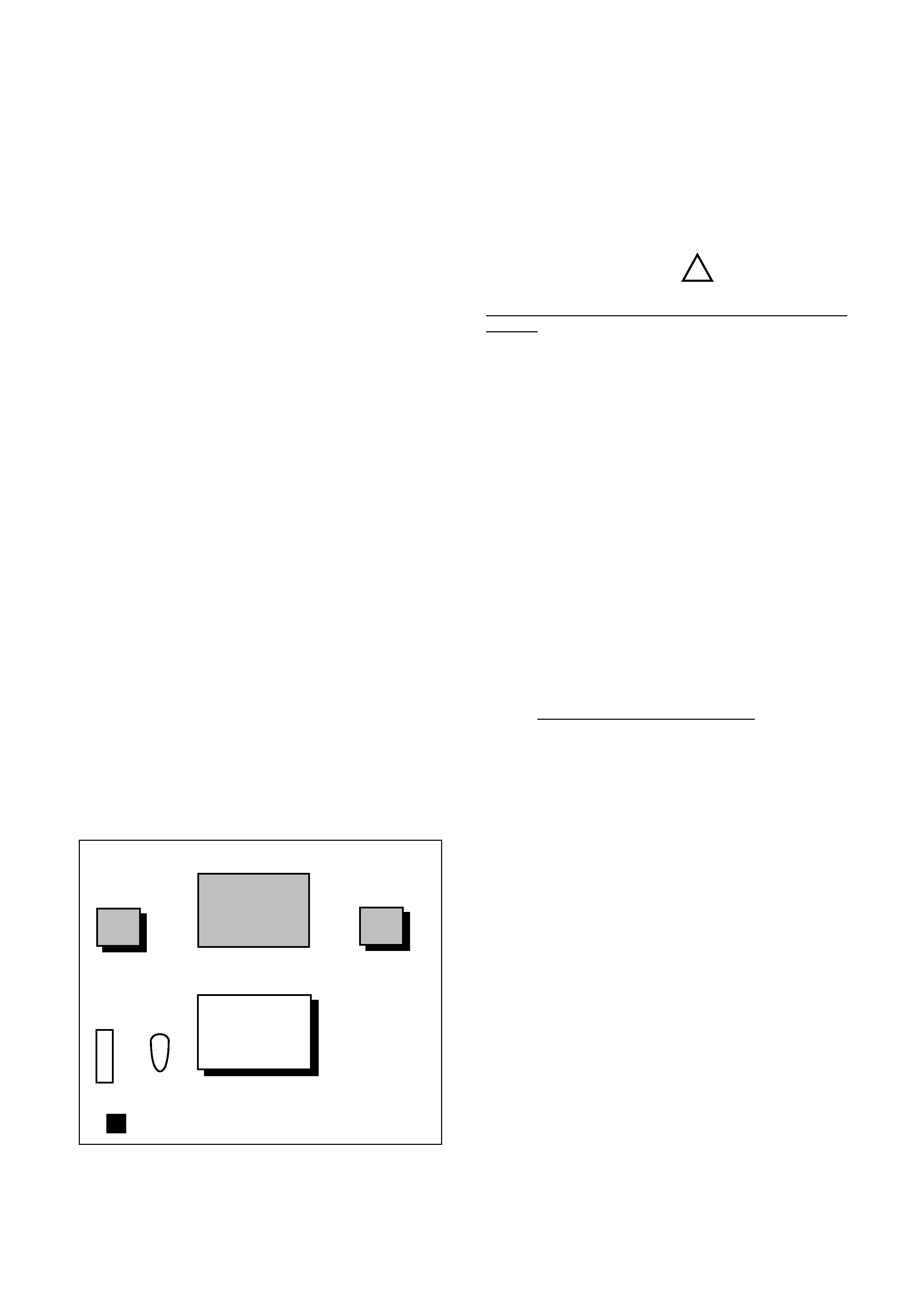
1.3. Cautions/Warnings
(1)
Product Safety Notice
Parts marked with the symbol
in the schematic
diagram have critical characteristics.
Use ONLY replacement parts recommended by the manu-
facturer. It is recommended that the unit be operated from a
suitable DC supply or batteries during initial check-out pro-
cedures.
(2)
Leakage Current Check/Resistance Check
Before returning the unit to the customer, make sure you
make either (1) a leakage current check or (2) a line to
chassis resistance check. If the leakage current exceeds
0.5 milliamp, or if the resistance from chassis to either side
of the power cord is less than 240 k ohms, the unit is defec-
tive.
WARNING -- DO NOT return the unit to the customer
until the problem is located and corrected.
(3)
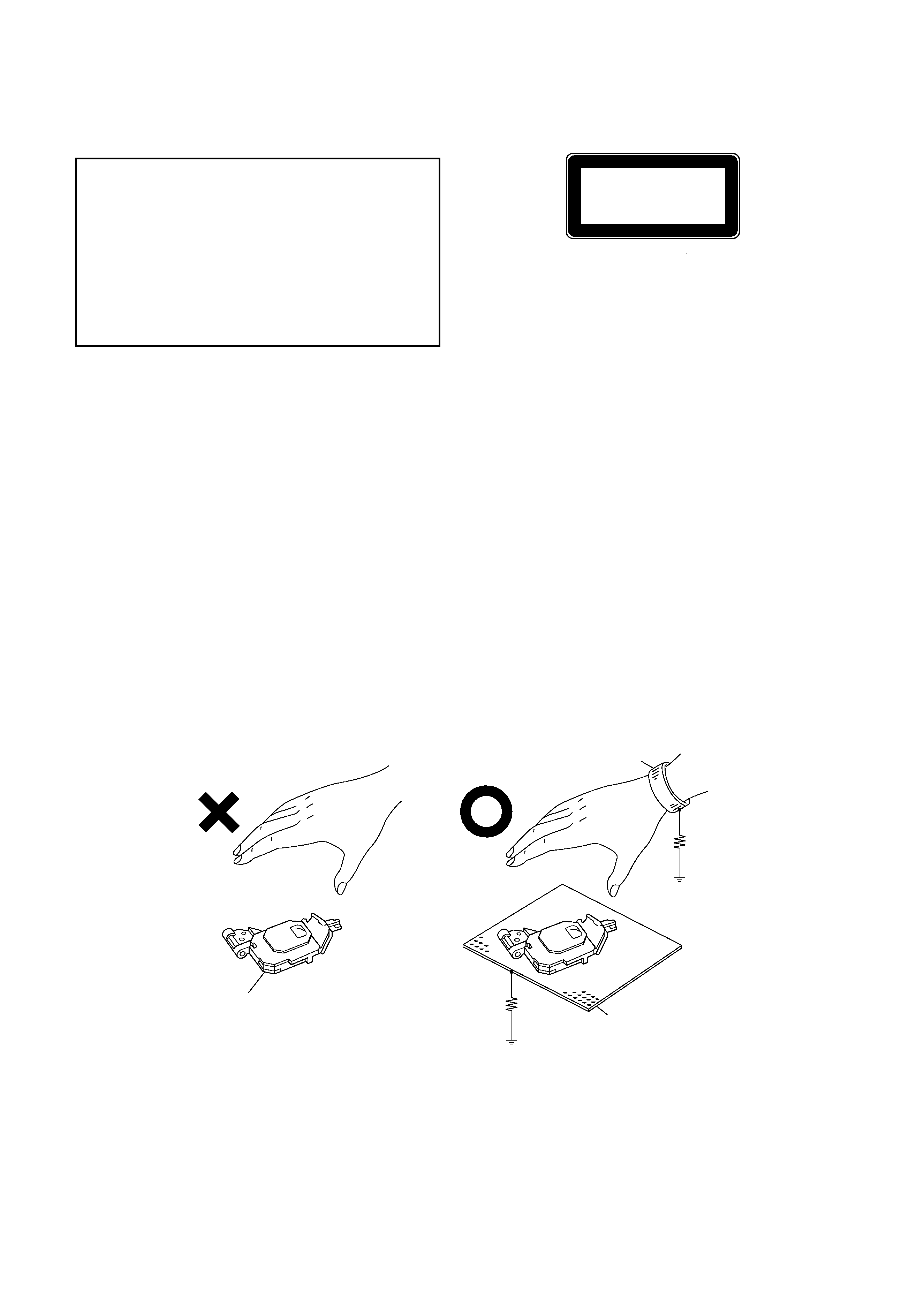
Protection of Eyes from Laser Beam
To protect eyes from invisible laser beam during servicing,
DO NOT LOOK AT THE LASER BEAM on the Changer.
(4)
Laser Caution
CAUTION
Adjusting the knobs, switches, and controls, etc. or taking
actions not specified herein may result in a harmful emis-
sion of laser beams. This CD Player must be adjusted and
repaired only by qualified service personnel.
OBSERVERA!
Sådana inställningar av rattarna, omkopplarna eller övriga
kontrollknappar som inte är beskriva i bruksanvisningen
kan resultera i farlig laserutstrålning. Justering eller repara-
tion av denna kompaktskivspelare skall endast utföras av
kvalificerad servicepersonal.
OBS!
Indstilling af knapper, cmskiftere og øvrige kontrolknapper,
som ikke følger den i brugsanvisningen beskrevne måde,
kan resultere i farlig laserudstråling. Justering eller repara-
tion af denno CD-afspiller må kun udføres af kvalificeret
servicepersonale.
OBS!
Justering av ratt, brytere og kontroller andre enn de som er
beskrevet her, kan resultere i farlig laserbestråling. Juster-
ing eller reparasjon av denne kompaktdiskspilleren ma
bare utføres av kvalifiserte fagfolk.
HUOMAUTUS
Jos nuppeja, kytkimiä ja säätimiä ym, säädetään tai laitetta
käytetään toisella tavalla kuin on selostettu, tuloksena saat-
taa olla vaarallista lasersäteiden vuotoa. CD-soittimen
säätö ja korjaus on jätettävä aina asiantuntevan
huoltoteknikon tehtäväksi.
!
Subwoofer
Speaker L
Main Unit
· Tuner
· CD Player x 3
Speaker R
Remote Control
(Main)
(Sub)
: Floor Stand (Option)
· Power Amp.
· Power Supply
q Floor Stands (Option)
· Floor stand for Main Unit
· Floor stand for Satellite Speakers L/R
background image
SS-9 General
iii
ADVERSEL: USYNLIG LASERSTRÅLING VED ÅBNING.
UNDGÅ UDSAETTELSE FOR STRÅLING.
VARO!:
AVATTAESSA OLET ALTTIINA
NÄKYMÄTTÖMÄLLE
LAS-
ERSÄTEILYLLE.
ÄLÄ KATSO SÄTEESEEN.
VARNING -- OSYNLIG LASERSTRÅLNING NAR
DENNA DEL ÄR ÖPPNAD. BETRAKTA
EJ STRÅLEN.
1.4. Handling the Laser Pickup
In case of repair or replacement of the Laser Pickup, pay
attention to the following handling instructions since the la-
ser diode in the Laser Pickup is not resistant to static elec-
tricity.
(1)
Grounding
When you repair a Laser Pickup, first ground the hu-
man body, as well as the measuring instruments and
other tools (with particular caution to soldering iron).
What's more, your workbench and floor should desir-
ably be grounded using conductive sheet or copper
plate. See Fig. 1.2.
NOTE: Be careful so as not to let your clothes touch
the Laser Pickup, as static electricity on the
clothes will not be released even if your body
is grounded.
THIS COMPACT DISC PLAYER IS CLASSIFIED
AS A CLASS 1 LASER PRODUCT.
THE CLASS 1 LASER PRODUCT LABEL IS
LOCATED ON THE REAR EXTERIOR.
CLASS 1
LASER PRODUCT
(2)
Discharge of Electricity
Be sure to discharge electricity from objects brought into
contact with the Laser Pickup (i.e., soldering iron, tweezers,
probes, volt-ohm-meter probes, etc.) before starting work
by contacting them with the body chassis. Besides, never
touch the Laser Pickup while power is applied.
(3)
Soldering Iron to be Used
The soldering iron for use in repair work should be: (1) a
ceramic soldering iron, (2) a soldering iron with its metal
part grounded, or (3) a soldering iron whose insulation re-
sistance after five minutes of power application is 10 M-ohm
or more at 500 VDC. Soldering should be completed
promptly, at a soldering iron temperature of 320
° max (39
W). A soldering iron heated above this temperature can
break down the laser diode.
Fig. 1.2 Handling the Laser Pickup
(NO GOOD)
(GOOD)
1M
Conductive Sheet or
Copper Plate
Wrist-strap
for Grounding
Laser Pickup
1M
background image
SS-9 General
iv
Schematic
Ref. No.
Part No.
Description
Q'ty
1.5. Package Ass'y and Accessory Ass'y
(1) Main Unit
--
Package & Accessory Ass'y
(Main Unit)
01
0F05628A
Carton Box
1
02
0F05630A
Packing Bottom Center
1
03
0F05629A
Packing Top Center
1
--
0F05631A
Accessory Box
1
--
0F05689A
Soft Sheet D Top A
1
--
0F05690A
Soft Sheet D Top B
2
--
0F05692A
Soft Bag Center
1
--
0F05693A
Soft Bag Stand Top
3
--
0B85619A
13P DIN Cable 5m
1
--
0B85620A
3P RCA Cable 5m
1
--
0B90462A
Battery UM4x1
4
--
0B90819A
FM Indoor Antenna
1
--
0B90820A
Antenna Adaptor
1
(JPN, OTR, USA, CAN, DA, TW)
--
0B91071A
Antenna Adapter EP
1
(UK, AUS, EP, CH, HK, KR)
--
0D03092B
Poly Bag
1
--
0D07105A
Speaker Cable
2
--
0D07238A
AC Cord UL (USA, CAN)
1
--
0D07239A
AC Cord EP (EP)
1
--
0D07240A
AC Cord DA/DU (OTR, DA, TW)
1
--
0D07241A
AC Cord DM (JPN)
1
--
0D07242A
AC Cord BS/HK (UK, HK)
1
--
0D07243A
AC Cord CH (CH)
1
--
0D07244A
AC Cord KR (KR)
1
--
0D07245A
AC Cord SA (AUS)
1
--
0D07371B
Owner's Manual Japanese
1
--
0D07372B
Owner's Manual English
1
--
0D07375A
Template
1
--
0D07376A
Owner's Manual Korean
1
--
0D07450A
Owner's Manual French
1
--
0D07451A
Owner's Manual German
1
--
0D07452B
Owner's Manual Spanish
1
--
0D07453A
Owner's Manual Italian
1
--
0D07454A
Template Speaker
1
--
0D07477A
AM Loop Antenna
1
--
0F05693A
Soft Bag Stand Top
1
--
0H08216A
CD Single Adaptor (JPN)
1
--
0H08749A
Cable Holder
1
--
0H09008E
Stand Holder Cover Center
1
--
0H09012A
Stand Pole Cover L67
1
--
0H09013A
Stand Pole Cover L82
2
--
0H09031A
Base Cover Center DT
1
--
0J08862A
Pole Cover Cushion
1
--
DA05574A Screw Ass'y D210
1
--
DG05310A Remote Control Sub Ass'y SS--5
1
--
HA08444A Main Remote Ass'y SS9
1
(Except UK, EP)
--
HA08447A Main Remote Ass'y RDS SS9 (UK, EP) 1
Fig. 1.3 Main Unit
01
02
03
background image
SS-9 General
v
(2) Subwoofer and Satellite Speakers
Fig. 1.4 Subwoofer and Satellite Speakers
--
Package and Accessory Ass'y
(Subwoofer and Satellite Speakers)
01
0F05694A
Carton Box S369
1
02
0F05703A
Packing Bottom Subwoofer
1
03
0F05702A
Packing Top Subwoofer
1
04
0F05691A
Soft Sheet Subwoofer
1
05
0F05541A
Soft Bag Satellite
2
--
DA05647A Screw Ass'y S369
1
--
DA05648A Spacer Ass'y S369
1
Schematic
Ref. No.
Part No.
Description
Q'ty
01
04
05
02
03

Reviews

There are no reviews of this manual yet.