NAKAMICHI PA5 Service Manual

Cover page of NAKAMICHI PA5 Service Manual

Service Manual for NAKAMICHI PA5, downloadable as a PDF file.

Manual details

  • Immediate download after payment.
  • Delivered as a PDF file.
  • The manual has 70 pages
  • File size: 13.87 MB
  • Available language versions: English
  • Different language versions may vary sligthly in file size and page count.

We guarantee that...

  • our manuals are complete,
  • the manual includes circuit diagrams,
  • our manuals are checked with antivirus,
  • We'll issue refund if the manual is damaged, incomplete or unreadable (our refund policy)

Sample pages

Thumbnail of page 1Thumbnail of page 2Thumbnail of page 3Thumbnail of page 4
Thumbnail of page 5Thumbnail of page 6Thumbnail of page 7Thumbnail of page 8
Thumbnail of page 9
background image
Zusätzlich erforderliche
Unterlagen für den Komplettservice
Additionally required
Service Manuals for the Complete Service
Service
Manual
Service
Manual
Service Manual
HiFi
PA 5 - Turnit
Btx * 32700 #
Sachnummer
Part Number 72010 758 0500
Änderungen vorbehalten
Subject to alteration
Printed in Germany
VK233 0598
PA 5 - Turnit
Sach-Nr./Part No.
72010 758 0500
Sicherheit
Safety
Sach-Nr./Part No.
72010-800.00
Grundig Service
Hotline Deutschland...
TV/SAT
VCR/LiveCam
HiFi/Audio
Car Audio
Telekommunikation
Fax:
0180/52318-41
0180/52318-42
0180/52318-43
0180/52318-44
0180/52318-45
0180/52318-51
...Mo.-Fr. 8.00-16.30 Uhr
Ersatzteil-Bestellannahme:
0180/52318-40
0180/52318-50
Telefon:
Fax:
Technik:
background image
Allgemeiner Teil / General Section
PA 5 - Turnit
1 - 2
GRUNDIG Service
Es gelten die Vorschriften und Sicherheitshin-
weise gemäß dem Service Manual "Sicherheit",
Sach-Nummer 72010-800.00, sowie zusätzlich
die eventuell abweichenden, landesspezifischen
Vorschriften!
The regulations and safety instructions shall be
valid as provided by the "Safety" Service Manual,
part number 72010-800.00, as well as the
respective national deviations.
GB
Table of Contents
Page
General Section ........................... 1 - 3 ... 1 - 33
Test Equipment / Aids ............................................................... 1 - 3
Service Hint ............................................................................... 1 - 3
Technical Data .......................................................................... 1 - 3
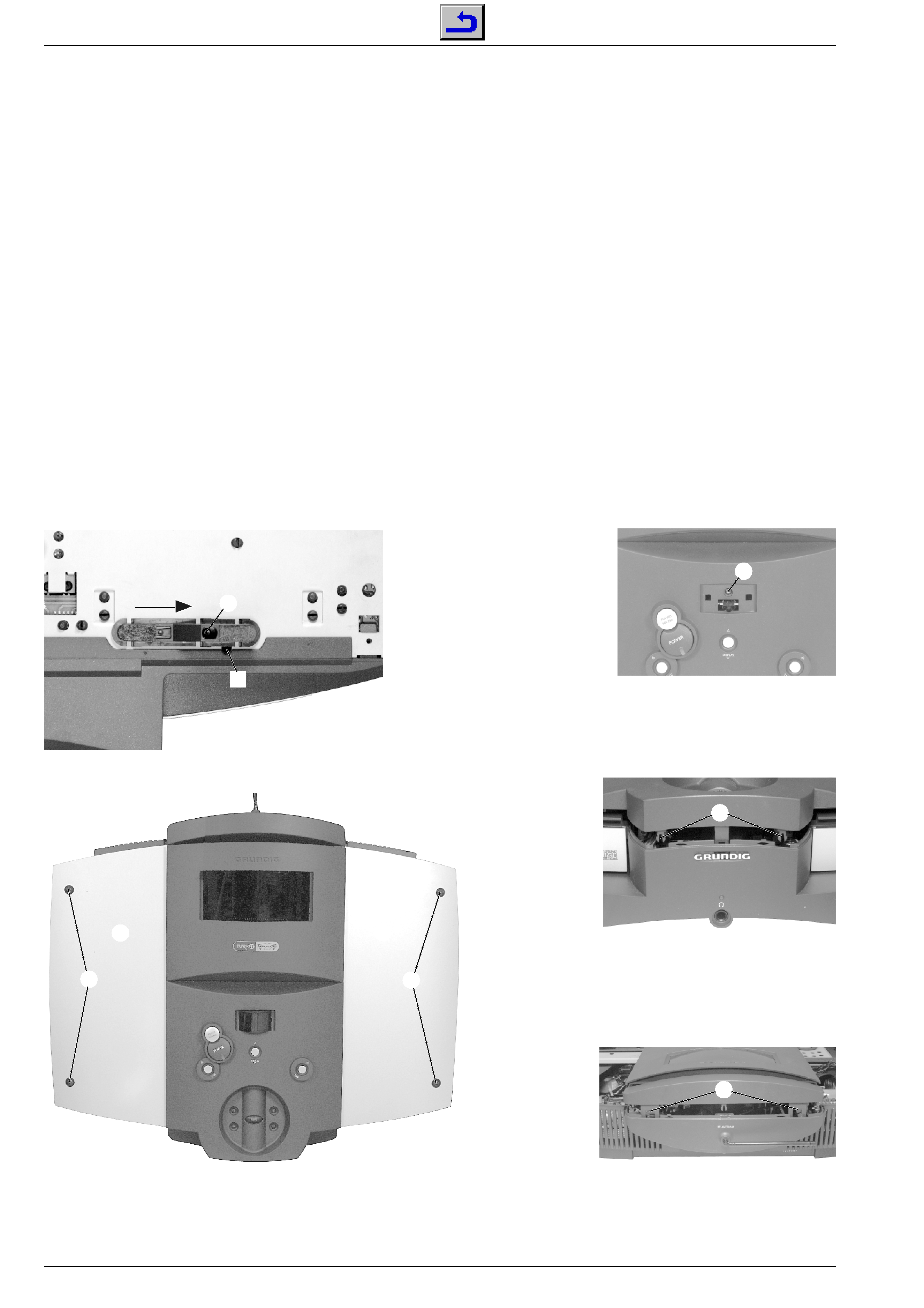
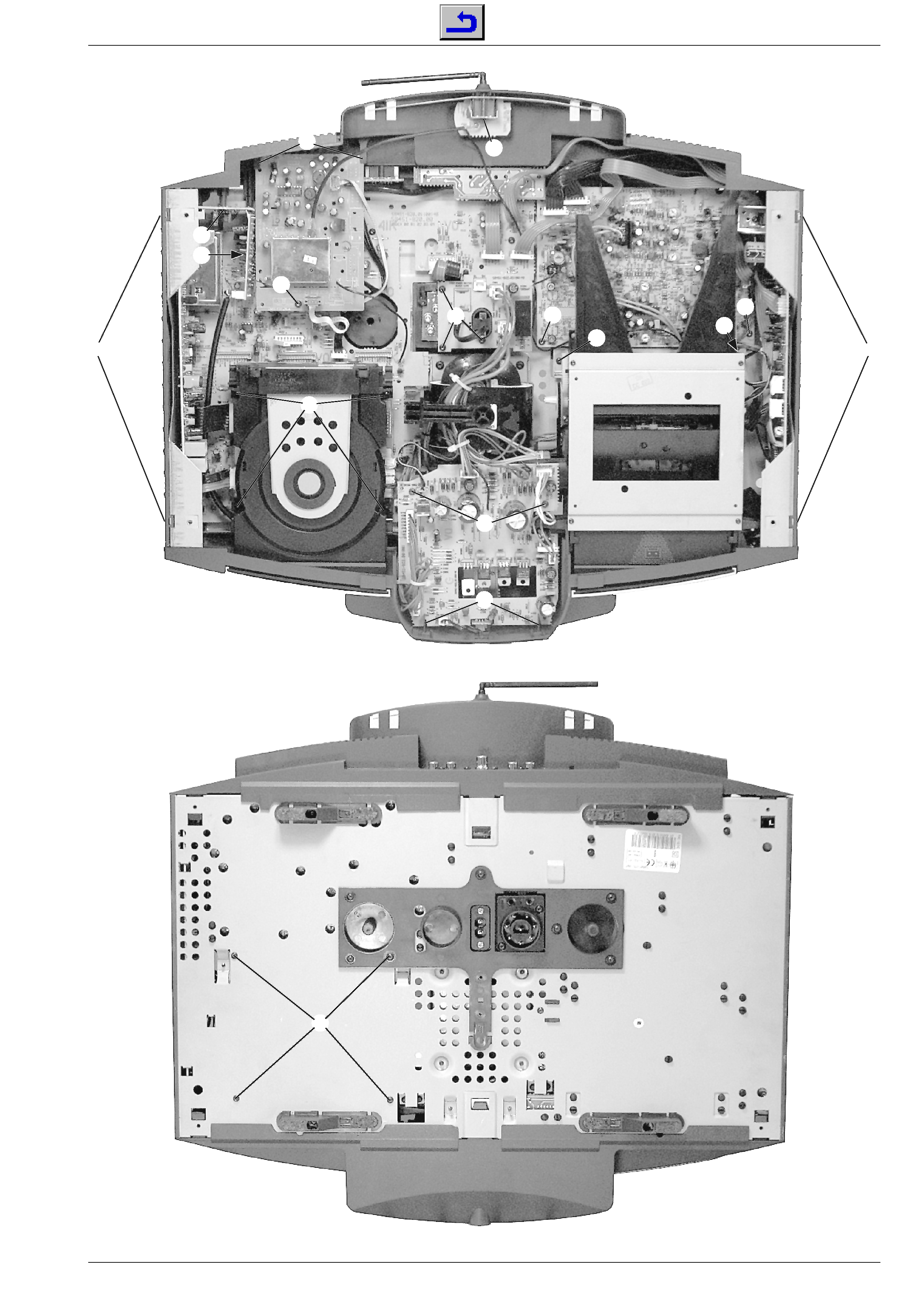
Disassembly Instructions .......................................................... 1 - 4
Operating Hints ....................................................................... 1 - 26
Adjustment Procedures ................ 2 - 1 ... 2 - 7
Circuit Diagrams
and Layout of PCBs .................... 3 - 1 ... 3 - 44
General Block Diagram ............................................................. 3 - 1
Notes on Components .............................................................. 3 - 2
Circuit Diagrams Control Unit
Block Diagram ....................................................................... 3 - 3
Main Board, I/O Board, Amplifier Board ................................ 3 - 5
Main Board, Headphone Board, Audio Plug Board ............... 3 - 7
Main Board ............................................................................ 3 - 9
Main Board, Switch Board, Antenna Board, Keys Boards,
Display Detector Board, IR Board, Motor Board .................. 3 - 11
Supply Board, LED Board, Regulator Board,
Mains Board, Power Switch Board ...................................... 3 - 13
Tape Audio Board ................................................................ 3 - 15
Tape Logic Board, Detector Board, Dolby LED Board ........ 3 - 17
CD Board ............................................................................. 3 - 19
Pick Up Unit ......................................................................... 3 - 43
Display ................................................................................. 3 - 21
Tuner ................................................................................... 3 - 23
Layout of PCBs Control Unit
Main Board, Audio Plug Board, Motor Board,
Power Switch Board, I/O Board, Amplifier Board ................ 3 - 27
Tape Audio Board, Tape Logic Board, Detector Board,
Dolby LED Board, Antenna Board, Mains Board, Keys Board,
Switch Board, Display Board, Headphone Board ................ 3 - 29
Supply Board, IR Board, LED Board, Display Detector Board,
Regulator Board, CD Board, Tuner ..................................... 3 - 31
Circuit Diagrams Sound Unit
Block Diagram ..................................................................... 3 - 33
Control Board, Power Switch Board, AC Filter Board,
AC Outlet Board, Potentiometer Board,
Audio Plug Boards ............................................................... 3 - 35
Control Board, Mute LED Board,
Stby LED Board, LED Board ............................................... 3 - 37
Audio Amplifier Boards ........................................................ 3 - 39
Layout of PCBs Control Unit ................................................... 3 - 41
IC Block Diagrams .................................................................. 3 - 43
Display .................................................................................... 3 - 44
Spare Parts Lists and
Exploded Views ............................. 4 - 1 ... 4 - 8
Exploded View Control Unit ...................................................... 4 - 1
Spare Parts List Control Unit .................................................... 4 - 2
Exploded View Sound Unit ....................................................... 4 - 4
Spare Parts List Sound Unit ...................................................... 4 - 5
Exploded View CD Drive ........................................................... 4 - 6
Spare Parts List CD Drive ......................................................... 4 - 8
Exploded View Tape Drive ........................................................ 4 - 7
Spare Parts List Tape Drive ...................................................... 4 - 8
D
Inhaltsverzeichnis
Seite
Allgemeiner Teil .......................... 1 - 3 ... 1 - 26
Meßgeräte / Hilfsmittel .............................................................. 1 - 3
Servicehinweis .......................................................................... 1 - 3
Technische Daten ..................................................................... 1 - 3
Ausbauhinweise ........................................................................ 1 - 4
Bedienhinweise ....................................................................... 1 - 19
Abgleichvorschriften .................... 2 - 1 ... 2 - 7
Schaltpläne und
Druckplattenabbildungen ........... 3 - 1 ... 3 - 44
Gesamtblockschaltplan ............................................................. 3 - 1
Bauteilhinweise ......................................................................... 3 - 2
Schaltpläne Steuereinheit
Blockschaltplan ...................................................................... 3 - 3
Hauptplatte, I/O-Platte, Verstärkerplatte ................................ 3 - 5
Hauptplatte, Kopfhörerplatte, Audio Verbindungsplatte ......... 3 - 7
Hauptplatte ............................................................................ 3 - 9
Hauptplatte, Schalterplatte, Antennenplatte, Tastenplatten,
Display-Detektor-Platte, IR-Empfänger-Platte, Motorplatte . 3 - 11
Stromversorgnungsplatte, LED-Platte, Reglerplatte,
Netzplatte, Netzschalterplatte .............................................. 3 - 13
Cassetten-Audio-Platte ........................................................ 3 - 15
Cassetten-Steuerungs-Platte,
Detektor-Platte, Dolby-LED-Platte ....................................... 3 - 17
CD-Platte ............................................................................. 3 - 19
Pick-Up-Einheit .................................................................... 3 - 43
Display ................................................................................. 3 - 21
Tuner ................................................................................... 3 - 23
Druckplattenabbildungen Steuereinheit
Hauptplatte, Audio Verbindungsplatte, Motorplatte,
Netzschalterplatte, I/O-Platte, Verstärkerplatte ................... 3 - 27
Cassetten-Audio-Platte, Cassettet-Steuerungs-Platte,
Detektor-Platte, Dolby-LED-Platte, Antennenplatte,
Netzplatte, Tastenplatte, Schalterplatte,
Display-Platte, Kopfhörerplatte ............................................ 3 - 29
Stromversorgnungsplatte, IR-Empfänger-Platte, LED-Platte,
Display-Detektor-Platte, Reglerplatte, CD-Platte, Tuner ..... 3 - 31
Schaltbilder Klangeinheit
Blockschaltplan .................................................................... 3 - 33
Kontrollplatte, Netzschalterplatte, Netzfilterplatte,
AC-Ausgangsplatte, Potentiometerplatte,
Audio-Verbindungsplatten ................................................... 3 - 35
Kontrollplatte, Mute-LED-Platte,
Stby-LED-Platte, LED-Platte ................................................ 3 - 37
Audio-Verstärker-Platten ..................................................... 3 - 39
Druckplattenabbildungen Klangeinheit ................................... 3 - 41
IC-Innenbeschaltungen ........................................................... 3 - 43
Display .................................................................................... 3 - 44
Ersatzteillisten und
Explosionszeichnungen ............... 4 - 1 ... 4 - 8
Explosionszeichnung Steuereinheit .......................................... 4 - 1
Ersatzteilliste Steuereinheit ....................................................... 4 - 2
Explosionszeichnung Klangeinheit ........................................... 4 - 4
Ersatzteilliste Klangeinheit ........................................................ 4 - 5
Explosionszeichnung CD-Laufwerk .......................................... 4 - 6
Ersatzteilliste CD-Laufwerk ....................................................... 4 - 8
Explosionszeichnung Cassettenlaufwerk .................................. 4 - 7
Ersatzteilliste Cassettenlaufwerk .............................................. 4 - 8
background image
PA 5 - Turnit
Allgemeiner Teil / General Section
GRUNDIG Service
1 - 3
Servicehinweis
Die HF-Sender- und Empfängerteile dürfen nur durch autorisierte
Fachbetriebe repariert werden und müssen daher im Defektfall
komplett getauscht werden.
Service Hint
The RF Transmitter and Receiver are allowed to be repaired only
by authorized dealers and are to be exchanged completely in case
of any defect.
Technische Daten
Verstärker
Ausgangsleistung (DIN45500) Sinus/Musik (4
):
Bass ................................................................. 2 x 40W / 2 x 75W
Middle+Treble .................................................. 2 x 40W / 2 x 75W
Klirrfaktor: Sinusleistung -1dB, 1kHz ..................................... 0,01%
Geräuschspannungsabstand ................................................... 95dB
Übertragungsbereich Line in ..................................... 5Hz ... 100kHz
Eingangsempfindlichkeit/Impedanz ........................... 300mV / 47k
Tuner
Empfindlichkeit
Mono (S/N = 26dB) .............................................................. 1,6
µV
Stereo (S/N = 46dB) .............................................................. 31
µV
Distortion
Mono (1kHz, 40/75kHz Hub) ........................................... 0,2/0,4%
Stereo (1kHz, 40/75kHz Hub) ......................................... 0,4/0,7%
Frequenzbereich (-3dB) ............................................ 10Hz ... 15kHz
Stereo Crosstalk (1kHz) ............................................................ 40dB
Dynamische Trennschärfe
(mono, stereo,
± 300kHz) ................................................. 60/60dB
Geräuschspannungsabstand
Mono 40kHz Hub, DIN A ....................................................... 74dB
Stereo 40kHz Hub, DIN A ..................................................... 70dB
Empfangsbereich
FM (25kHz) ...................................................... 87,5 ... 108,0MHz
CD-Spieler
Frequenzgang (
± 0.5dB) ........................................... 20Hz ... 20kHz
Klirrfaktor (0dB, 1kHz) ........................................................... 0,008%
Geräuschspannungsabstand (`A' gewichtet) ......................... 100dB
Cassettendeck
Frequenzbereich ....................................................... 40Hz ... 16kHz
Geräuschspannungsabstand (IEC gewichtet, Cr)
Dolby B .................................................................................. 64dB
Dolby aus .............................................................................. 56dB
Gleichlaufschwankungen (IEC gewichtet) ............................. 0,13%
Stereo Crosstalk (1kHz) ............................................................ 40dB
System
Spannungsversorgung:
Betriebsspannung ............................................................... 230V~
Frequenz .......................................................................... 50/60Hz
max. Leistungsaufnahme ..................................................... 300W
Leistungsaufnahme in Standby ............................................. 7,5W
Technical Data
Amplifier
Output power (DIN45500) Nominal/Music (4
):
Bass ................................................................. 2 x 40W / 2 x 75W
Middle + treble .................................................. 2 x 40W / 2 x 75W
Distortion: Nominal power -1dB, 1kHz .................................... 0.01%
Signal-to-noise ratio .................................................................. 95dB
Frequency response Line in ...................................... 5Hz ... 100kHz
Input sensitivity / impedance ...................................... 300mV / 47k
Tuner
Sensitivity
Mono (S/N = 26dB) .............................................................. 1.6
µV
Stereo (S/N = 46dB) ............................................................. 31
µV
Distortion
Mono (1kHz, 40/75kHz dev.) ........................................... 0.2/0.4%
Stereo (1kHz, 40/75kHz dev.) ......................................... 0.4/0.7%
Frequency response (-3dB) ...................................... 10Hz ... 15kHz
Stereo Crosstalk (1kHz) ............................................................ 40dB
Dynamic selectivity
(mono, stereo,
± 300kHz) ................................................. 60/60dB
Signal-to-noise ratio
Mono 40kHz dev., DIN A ....................................................... 74dB
Stereo 40kHz dev., DIN A ..................................................... 70dB
Frequency ranges
FM (25kHz steps) ............................................. 87.5 ... 108.0MHz
CD player
Frequency response (
± 0.5dB) ................................. 20Hz ... 20kHz
Distortion (0dB, 1kHz) ........................................................... 0.008%
Signal-to-noise ratio (A wtd.) ................................................... 100dB
Cassette deck
Frequency response ................................................. 40Hz ... 16kHz
Signal-to-noise ratio (IEC wtd., Cr)
Dolby B .................................................................................. 64dB
Dolby off ................................................................................ 56dB
Wow & Flutter (IEC wtd.) ....................................................... 0.13%
Stereo Crosstalk (1kHz) ............................................................ 40dB
System
Power supply
Mains voltage ...................................................................... 230V~
Mains frequency ............................................................... 50/60Hz
Maximum power consumption ............................................. 300W
Standby power consumption ................................................. 7.5W
Allgemeiner Teil
Meßgeräte / Meßmittel
Meß-/Wobbelsender
Stereocoder
Tongenerator
Oszilloskop
Klirrfaktormeßgerät
DC-Voltmeter
NF-Voltmeter
Frequenzzähler
Tonhöhenschwankungsmesser
Testcassette 448A (Sach-Nr. 35079-023.00)
Drehmomentcassette 456 (Sach-Nr. 35079-014.00)
Beachten Sie bitte das GRUNDIG Meßtechnik-Programm, das Sie
unter folgender Adresse erhalten:
GRUNDIG Instruments
Test- und Meßsysteme GmbH
Würzburger Str. 150, D-90766 Fürth/Bay
Tel. 0911/703-4118, Fax 0911/703-4130
Internet: http://www.grundig.instruments.de
General Section
Test Equipment / Aids
Standard/sweep generator
Stereo coder
AF generator
Oscilloscope
Distortion meter
DC voltmeter
AF voltmeter
Frequency counter
Wow and flutter meter
Test cassette 448A (part no. 35079-023.00)
Torque test cassette 456 (part no. 35079-014.00)
Please note the Grundig Catalog "Test and Measuring Equipment"
obtainable from:
GRUNDIG Instruments
Test- und Meßsysteme GmbH
Würzburger Str. 150, D-90766 Fürth/Bay
Tel. 0911/703-4118, Fax 0911/703-4130
Internet: http://www.grundig.instruments.de
background image
Allgemeiner Teil / General Section
PA 5 - Turnit
1 - 4
GRUNDIG Service
Ausbauhinweise
Allgemeiner Hinweis:
Steckverbinder vor dem Abziehen markieren, da durch die große
Anzahl von gleichen Steckern Verwechslungsgefahr besteht. Beim
Zusammenbau ist aus Sicherheitsgründen darauf zu achten, daß die
Kabel wieder genauso verlegt werden wie vorher.
Manuelles Ausfahren der CD-Schublade:
siehe Pkt. 21.
Steuereinheit:
Gehäuse öffnen
- Die 4 Schrauben
A herausschrauben und die Abdeckungen B
abnehmen (Fig. 2).
- Die Schraube
C herausschrauben (Fig. 3).
- Die Rastnasen
D (Fig. 4) und E (Fig. 5) ausrasten und die
Bedieneinheit abheben.
- Bei Bedarf Steckverbindungen lösen.
1. Fuß ausbauen
- Schraube
F (Fig. 1) herausschrauben.
- Fuß in Pfeilrichtung schieben und abnehmen.
A
A
B
F
C
D
E
Fig. 1
Fig. 2
Fig. 3
Fig. 4
Fig. 5
B
N
Disassembly Instructions
General Hint:
Mark the connectors before pulling them off because they may easily
be confused because of the great number of identical connectors.
When reassembling take care, for safety reasons, that the cables are
laid in their original position.
To open the CD tray manually:
see para 21.
Control Unit:
Opening the case
- Undo 4 screws
A and remove the covers B (Fig. 2).
- Undo srew
C (Fig. 3).
- Unhook the catches
D (Fig. 4) and E (Fig. 5) and lift off the operating
part.
- Open connectors if necessary.
1. Removing a foot
- Undo screw
F (Fig. 1).
- Push foot in direction of the arrow and remove it.
background image
PA 5 - Turnit
Allgemeiner Teil / General Section
GRUNDIG Service
1 - 5
G
H
H
H
J
K
L
M
N
O
P
Q
R
R
T
T
Fig. 6
Fig. 7

Reviews

There are no reviews of this manual yet.