ENGLISH
FRANÇAIS
DEUTSCH
NEDERLANDS
ESP
AÑOL
IT
ALIANO
POR
TUGUÊS
SVENSKA
2
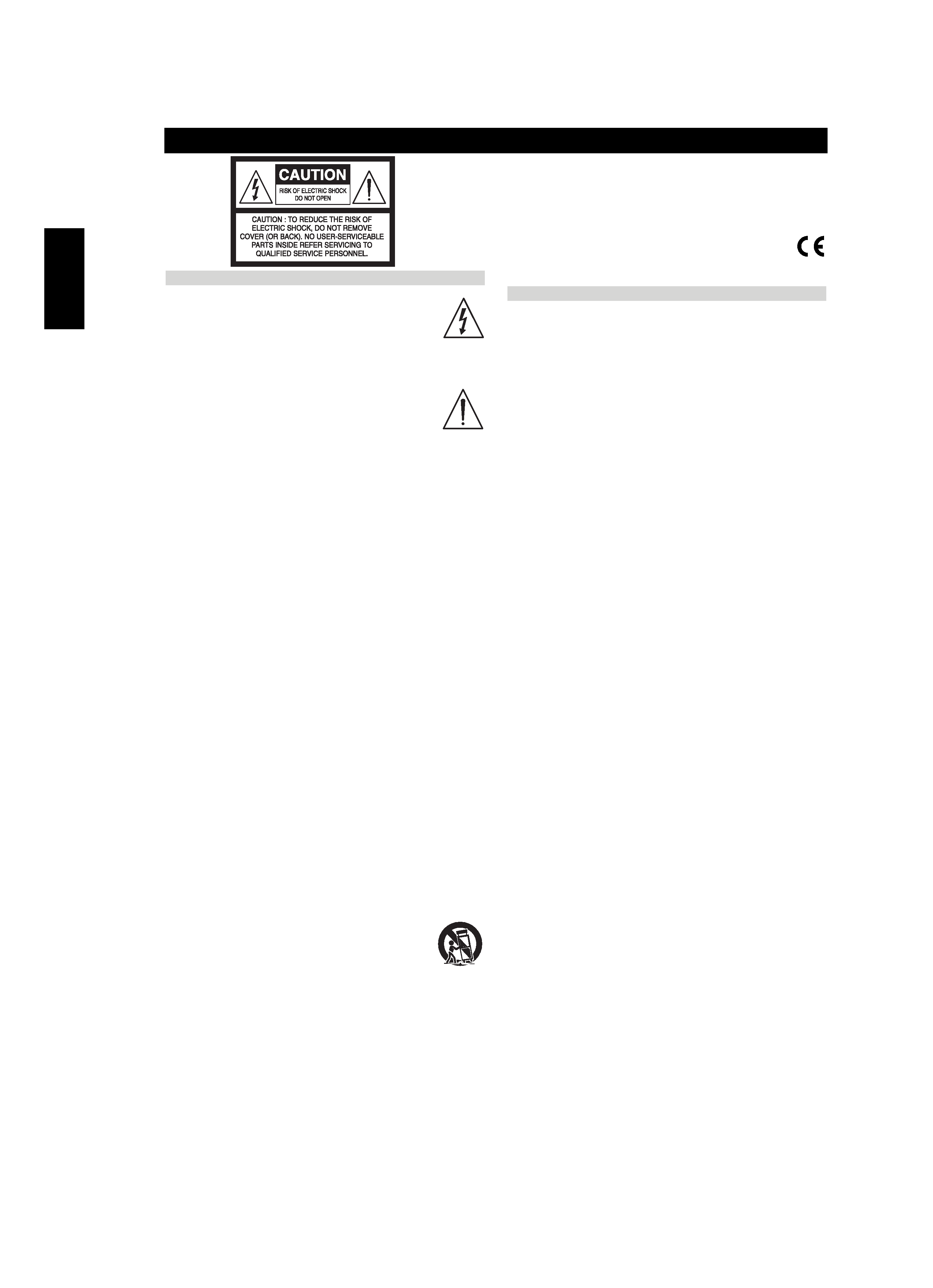
IMPORTANT SAFETY INSTRUCTIONS
EXPLANATION OF GRAPHICAL SYMBOLS
The lightning flash with arrowhead symbol, within an
equilateral triangle, is intended to alert the user to the presence
of uninsulated "dangerous voltage" within the product's
enclosure that may be of sufficient magnitude to constitute a
risk of electric shock to persons.
The exclamation point within an equilateral triangle is intended
to alert the user to the presence of important operating and
maintenance (servicing) instructions in the literature
accompanying the appliance.
PRECAUTIONS
Read the Operating Instructions carefully and completely before operating
the unit. Be sure to keep the Operating Instructions for future reference.
All warnings and cautions in the Operating Instructions and on the unit
should be strictly followed, as well as the safety suggestions below.
1 Read these instructions.
2 Keep these instructions.
3 Head all warnings.
4 Follow all instructions.
5 Do not use this apparatus near water or moisture.
6 Clean only with a dry cloth.
7 Do not block any ventilation openings. Install in accordance
with the manufacturer's instructions.
8 Do not install near any heat sources, such as radiators, heat
registers, stoves or other apparatus (including amplifiers) that
produce heat.
9 Do not defeat the safety purpose of the polarized or grounding-
type plug. A polarized plug has two blades with one wider
than the other.
A grounding-type plug as two blades and a
third grounding prong. The wider blade or third prong are
provided for your safety. If the provided plug does not fit in
your outlet, consult an electrician for replacement of the
obsolete outlet.
10 Protect the power cord from being walked on or pinched,
particularly at the plugs, convenience receptacles, and the point
where they exit from the apparatus.
11 Only
use
attachments/accessories
specified
by
the
manufacturer.
12 Us only with cart, stand. tripod, bracket or table
specified by the manufacturer or sold with the
apparatus. When a cart is used, use caution when
moving the cart/apparatus combination to avoid
injury from tip-over.
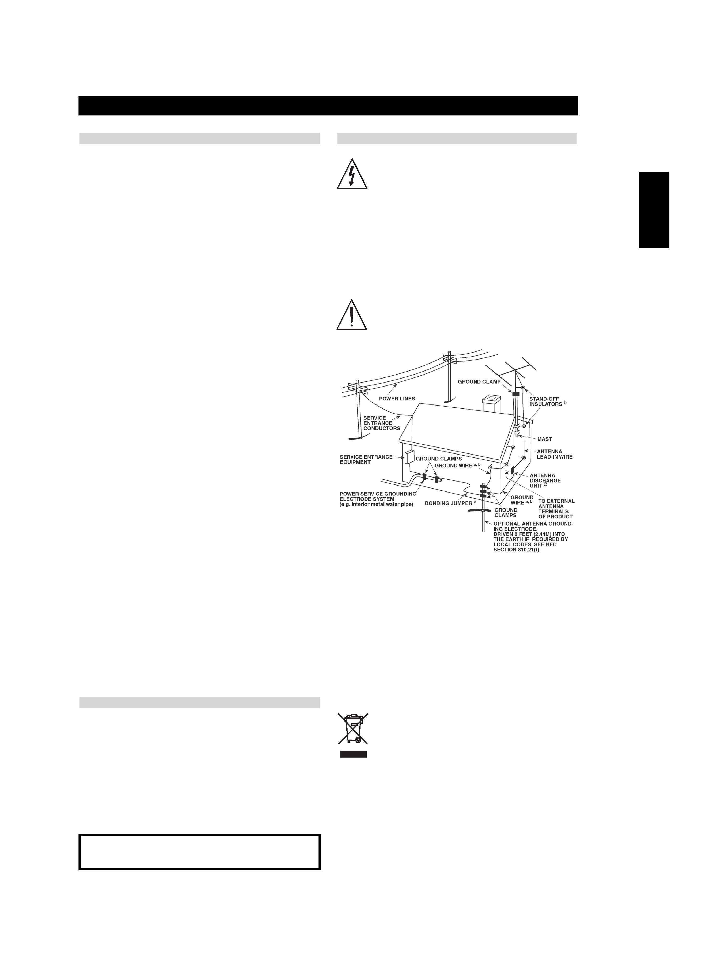
13 Unplug this apparatus during lightning storms or when unused
for long periods of time.
14 Refer all servicing to qualified service personnel. Servicing is
required when the apparatus has been damaged in any way:
such as power-supply cord or plug damage; liquid has been
spilled or objects have fallen into the apparatus; the apparatus
has been exposed to rain or moisture, does not operate
normally, or has been dropped.
15 The mains plug is used as the disconnect device, the disconnect
device shall remain readily operable.
WARNING! TO REDUCE THE RISK OF FIRE OR ELECTRONIC
SHOCK, DO NOT EXPOSE THIS APPLIANCE TO RAIN OR
MOISTURE
This product is manufactured to comply with the radio
interference requirements of EEC DIRECTIVE 89/68/EEC and
73/23/EEC
ELECTRIC POWER
1 Power Sources - Connect this unit only to power sources specified in
the Operating Instructions, and as marked on the unit.
2 Polarization - As a safety feature, some units are equipped with
polarized AC power plugs which can only be inserted one way into a
power outlet. If it is difficult or impossible to insert the AC power plug
into an outlet, turn the plug over and try again. If it still does not easily
insert into the outlet, please call a qualified service technician to service
or replace the outlet. To avoid defeating the safety feature of the
polarized plug, do not force it into a power outlet.
3 AC power cord - When disconnecting the AC power cord, pull it out
by the AC power plug. Do not pull the cord itself.
· Never handle the AC power plug with wet hands, as this could result
in fire or shock.
· Power cords should be routed to avoid being severely bent, pinched,
or walked upon. Pay particular attention to the cord from the unit to
the power socket.
· Avoid overloading AC outlets and extension cords beyond their
capacity, as this could result in fire or shock.
4 Extension cord - To help prevent electric shock, do not use a polarized
AC power plug with an extension cord, receptacle, or other outlet
unless the polarized plug can be completely inserted to prevent
exposure of the blades of the plug.
5 When not in use - Unplug the AC power cord from the AC outlet if
the unit will not be used for several months or more. When the cord is
plugged in, a small amount of current continues to flow to the unit,
even when the power is turned off.
CAUTION
Modifications or adjustments to this product, which are not expressly
approved by the manufacturer, may void the user's right or authority to
operate this product.
MAINTENANCE
Clean the unit only as recommended in the Operating Instructions.
DAMAGE REQUIRING SERVICE
Have the unit serviced by a qualified service technician if:
· The AC power plug has been damaged.
· Foreign objects or liquid have gotten inside the unit.
· The unit has been exposed to rain or water - The unit does not seem
to operate normally.
· The unit exhibits a marked change in performance.
· The unit has been dropped, or the cabinet has been damaged
DO NOT ATTEMPT TO SERVICE THE UNIT YOURSELF
VENTILATION
The unit should be situated with adequate space around it so that
proper ventilation is assured. allow 10 cm (4 in.) clearance from the
rear and the top of the unit, and 5 cm (2 in.) from each side. - Do not
place on a bed, rug, or similar surface that may block the ventilation
openings. - Do not install the unit in a bookcase cabinet, or airtight rack
where ventilation may be impeded.
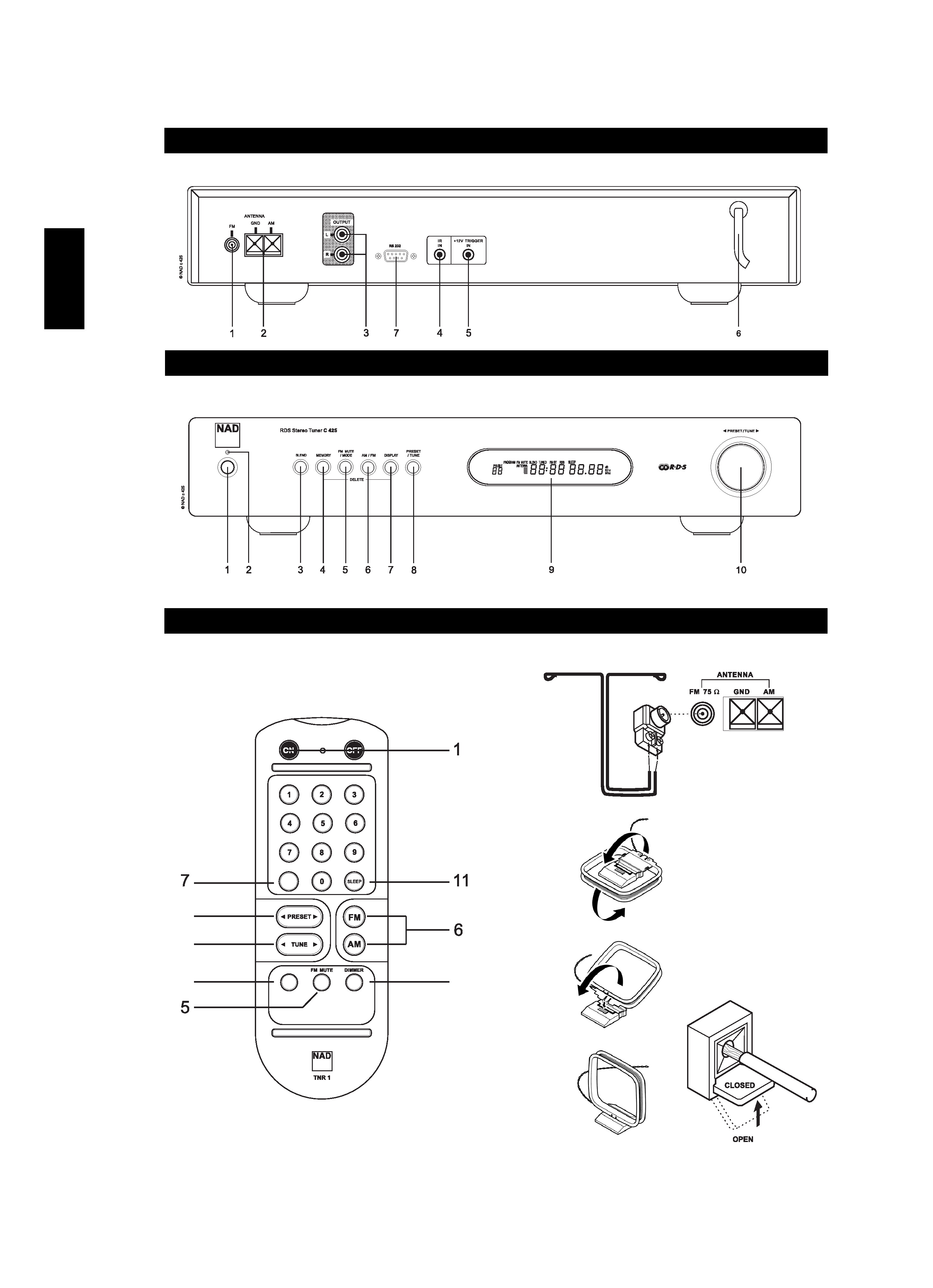
Introduction
C425 072006.qxd
7/28/2006
11:31 AM
Page 2