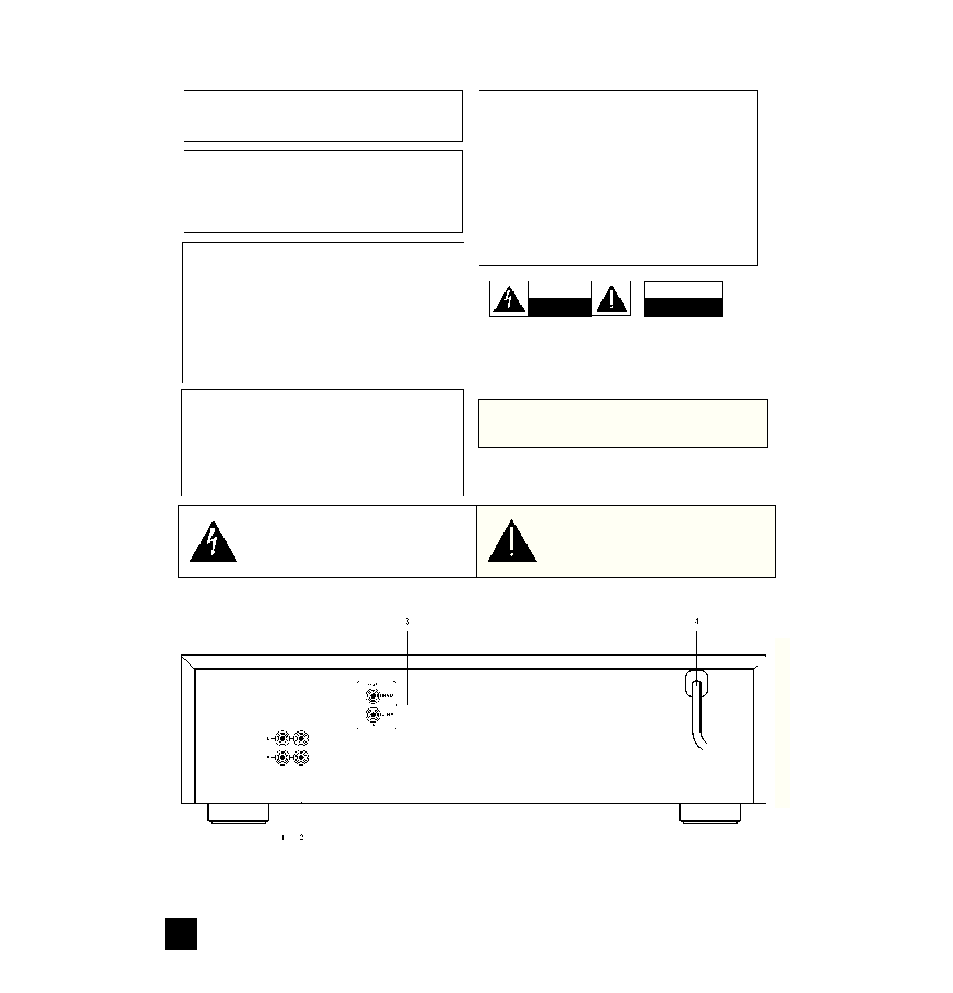
3. NAD LINK.
The "NAD Link IN" connector allows the NAD 616
to be operated by external remote control signals
passed from another NAD remote control component
featuring NAD Link, e.g. AV 716 receiver. NAD Link
works in a "daisy chain" fashion, connections going
from one unit to the next one. Many NAD receivers
and AV components come supplied as standard with
a NAD system remote control which has buttons for
most used tape transport functions (Play, Record,
Fast Forward, Rewind, Stop, etc.). Connect a cable
from the master unit Link Out (e.g. the AV 716) to the
NAD Link IN jack on the 616.
4. POWER.
Connect the AC mains cable to a convenient wall
socket or to an AC convenience outlet at the rear of
your amplifier or receiver.
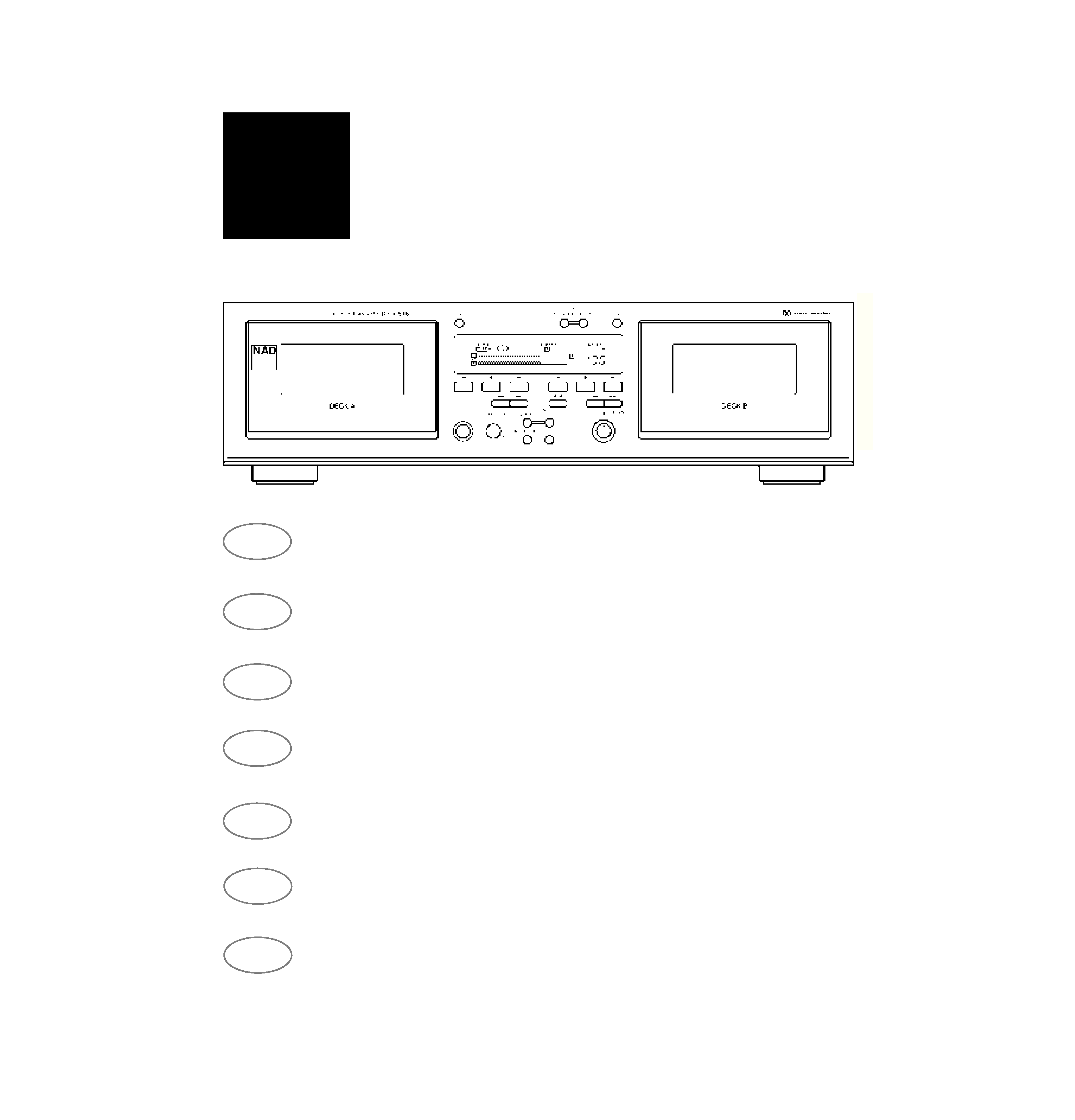
FRONT PANEL CONTROLS
The numbers in the text refer to the controls in fig-
ure "FRONT PANEL CONTROLS". Where buttons for
deck A and B perform identical functions these have
the same number with a suffix a or b, indicating which
deck the button relates to.
1. POWER.
Press this button to switch on the power to the cas-
sette deck. The display will light up and the Pause
icon "l l|" will flash for three seconds during which
time the deck will not respond to any commands. To
turn off the power, press again and release.
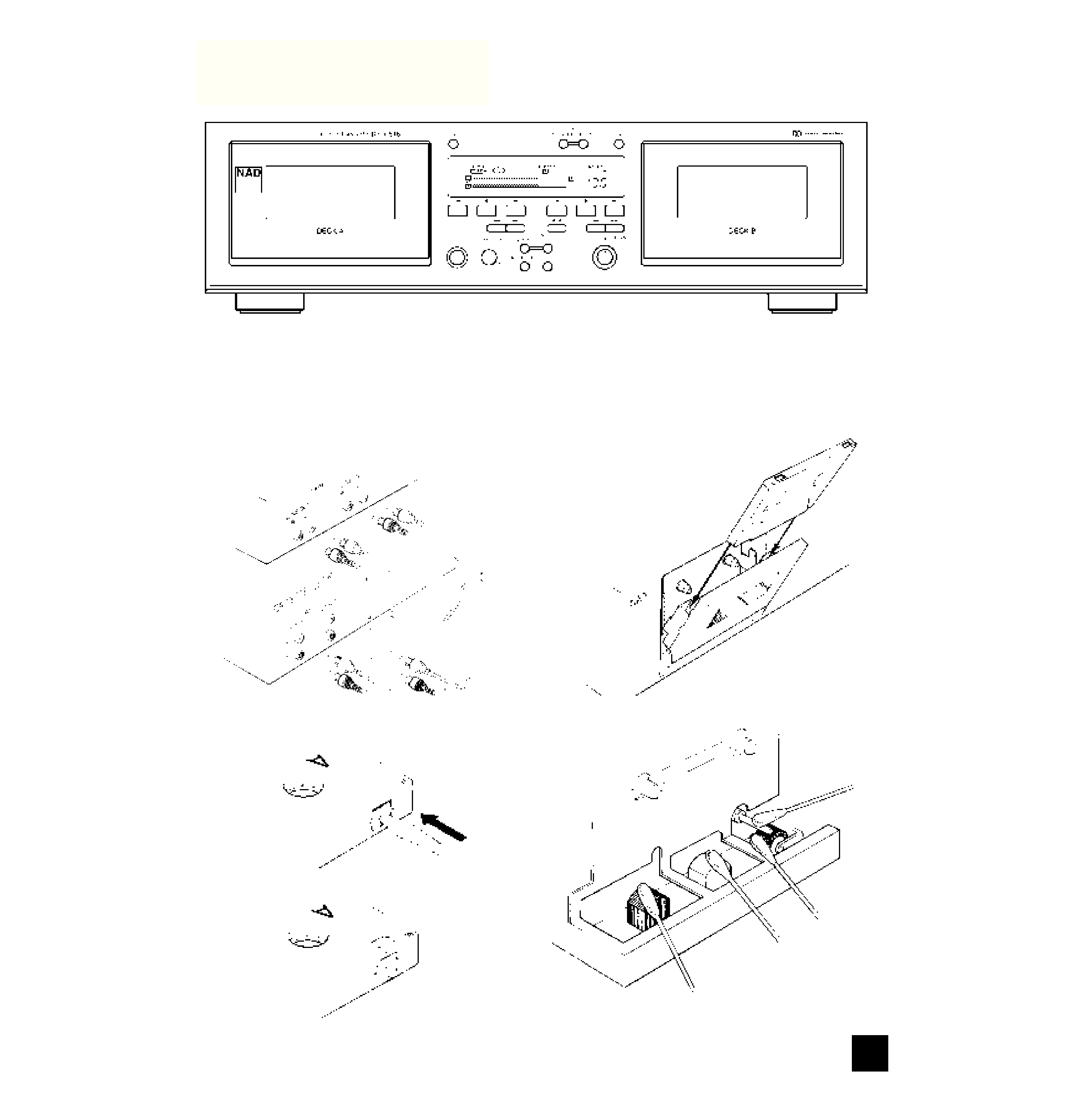
2 a+b. CASSETTE COMPARTMENTS.
The cassette tape must be inserted into one of
these compartments. Use the "OPEN" button to open
the compartment. With a gentle push, until a click is
heard, the compartment can be closed. Both the A
and B deck compartments allow for play back of a
tape. Only deck B can make recordings, however. As
both decks can play both sides of a tape we recom-
mend you consistently insert a tape into the compart-
ments with the first side facing forward. This way you
avoid confusion over what is the reversed side of the
tape and reversed play-back.
3 a+b. OPEN.
When this button is pressed, the door of the cas-
sette compartment next to it swings open to allow a
tape to be inserted or to be removed. During play-
back or recording the door cannot be opened.
4 a+b. REVERSE PLAY.
Both the A and B cassette transports can play back
both sides of a tape by reversing the head and tape
transport direction. As both decks can play both sides
of a tape we recommend you consistently insert a
tape into the compartments with the first side facing
forward. This way you avoid confusion over what is
the reversed side of the tape and reversed play-back.
Press this button to start reverse play-back of a tape.
The reverse Play icon
for the corresponding trans-
port will light up in the display. Refer to the chapter
"How to get the best performance from your NAD 616
cassette deck", section "Playing back tapes" for more
information.
5 a+b. STOP.
This button will stop all tape transport functions
such as normal and reversed play, record, fast for-
ward and rewind. It will also disengage the Record-
pause and Play-pause mode.
6 a +b. PLAY.
To play-back a tape in the normal direction use this
button. The Play icon
for the corresponding trans-
port will light up in the display. Refer to the chapter
"How to get the best performance from your NAD 616
cassette deck", section "Playing back tapes" for more
information.
7. DECK A/B (TAPE COUNTER SELECTOR).
This button toggles to show the tape count for the
A or B deck. The "A" or "B" annunciator before the
counter indicates which tape count is showing. Press
the button to switch to the tape count for the other
deck. Every time the cassette recorder is switched
on the tape counter will default to deck A.
8. RESET.
Press this button to reset the tape counter to
"0000" for the transport A or B, as indicated in the
display. Before re-setting the counter, make sure the
right transport has been selected. Refer to the sec-
tion "Tape counter selector" above for more informa-
tion. The counter can be re-set at any point while a
tape is playing to mark a particular place on the tape.
The counter is re-set to 0000 for both transports after
power has been turned off as well.
9. RECORD LEVEL.
The recording level for both channels can be con-
trolled with the inner rotary control. The two horizon-
tal bars in the display give you an exact indication of
the record level during recording. The bars also work
during play-back. These recording level meters are
equipped with an automatic "Peak hold" facility which
will display the highest peak for one second, even if
the peak itself lasted only a fraction of a second to
facilitate accurate read-out. Refer to chapter "How to
get the best performance from your NAD 616 cas-
sette deck", section "Making a recording" for more
detailed information.
10. BALANCE.
The recording balance between left and right chan-
nel can be adjusted using the outer rotary control.
Normally this control is set at the 12 o'clock (centre
detent) position.
Refer to chapter "How to get the best performance
from your NAD 616 cassette deck", section "Making a
recording " for more information.
NAD
5
GB