MITSUBISHI LT4260 Service Manual

Cover page of MITSUBISHI LT4260 Service Manual

Service Manual for MITSUBISHI LT4260, downloadable as a PDF file.

Manual details

  • Immediate download after payment.
  • Delivered as a PDF file.
  • The manual has 54 pages
  • File size: 2.74 MB
  • Available language versions: English
  • Different language versions may vary sligthly in file size and page count.

We guarantee that...

  • our manuals are complete,
  • the manual includes circuit diagrams,
  • our manuals are checked with antivirus,
  • We'll issue refund if the manual is damaged, incomplete or unreadable (our refund policy)

Sample pages

Thumbnail of page 1Thumbnail of page 2Thumbnail of page 3Thumbnail of page 4
Thumbnail of page 5Thumbnail of page 6Thumbnail of page 7Thumbnail of page 8
Thumbnail of page 9
background image
MITSUBISHI DIGITAL ELECTRONICS AMERICA, INC.
9351 Jeronimo Road, Irvine, CA 92618-1904
Copyright © 2005 Mitsubishi Digital Electronics America, Inc.
All Rights Reserved
CAUTION:
Before servicing this chassis, it is important that the service person read the "SAFETY PRECAUTIONS" and
"PRODUCT SAFETY NOTICE" contained in this manual.
MITSUBISHIELECTRIC Ser
Ser
Ser
Ser
Service
vice
vice
vice
vice
Manual
Manual
Manual
Manual
Manual
2005
2005
2005
2005
2005
SPECIFICATIONS
LIQUID CRYSTAL DISPLAY TELEVISION
· Power
: 120V, 60Hz, 350W (Includes AC Outlet-100W)
Standby <5W
· LCD Panel
: Size - 42" diagonal, 16:9
: Resolution - 1366 x 768
: Pixel Pitch - 0.227mm x 0.681 mm x RGB
· Video Inputs
: 1 Composite or S-Video (NTSC)
1 Component (480i, 480p, 720p, 1080i)
1 HDMITM (480p, 720p, 1080i)
· PC Input
: 1 Mini D-sub 15 pin (VGA, SVGA, XGA, WXGA)
Horiz: 31.5-80KHz, Vert: 55-75 Hz
· Audio Inputs
: 1 Pair RCA (L&R) for Composite or S-Video
1 Pair RCA (L&R) for Component
1 Pair RCA (L&R) for DVI (Using HDMI Input)
1 3.5mm Mini-Jack for PC
· Outputs
: 1 Headphone, 3.5mm Mini-Jack
1 USB (Memory Card data to HD-6000 only)
1 RS-232C (Control data for HD-6000 only)
· Speakers : Left & Right (2 X 5W) Woofer (10W)
LT-4260
(L423FR)
· Weight and dimensions shown are approximate.
· Design specifications are subject to change without notice.
· HDMITM is a trademark of HDMI Licensing, LLC
With Stand: Height
Width
Depth
Weight
31.5"
44.1"
14.2"
108.0 lbs
W/O Stand or Height
Width
Depth
Weight
Speakers:
29.8"
44.1"
4.9"
77.6 lbs
· Cabinet Dimensions / Weight
The LT-4260 includes the L423FR, monitor and HD-6000, receiver controller.
This manual covers the L423FR, monitor.
For the receiver/controller, see the HD-6000 Service Manual
background image
background image
MODEL: L423FR
Page 3
CONTENTS
PRODUCT SAFETY NOTICE ............................................................................................................. 5
SAFETY PRECAUTIONS ................................................................................................................... 5
DISASSEMBLY
Cabinet Disassembly ...................................................................................................................... 7
Panel Replacement ....................................................................................................................... 13
Wire Dressing ............................................................................................................................... 18
ELECTRICAL ADJUSTMENTS
Initial Setup ................................................................................................................................... 19
CIRCUIT EXPLANATIONS & BLOCK DIAGRAMS
Circuit Explanations ...................................................................................................................... 20
Block Diagrams ............................................................................................................................ 25
TROUBLESHOOTING
Power Troubleshooting .................................................................................................................. 29
Video Troubleshooting ................................................................................................................... 31
Audio Troubleshooting ................................................................................................................... 34
Remote Control & Front Switch Troubleshooting ........................................................................... 36
REPLACEMENT PARTS
Replacement Parts List ................................................................................................................ 37
SCHEMATICS
background image
MODEL: L423FR
Page 4
background image
MODEL: L423FR
Page 5
PRODUCT SAFETY NOTICE
Many electrical and mechanical parts in television receivers have special safety related characteristics. These character-
istics are often not evident from visual inspection nor can the protection afforded by them necessarily be obtained by
using replacement components rated for higher voltage, wattage, etc.
Replacement parts which have special safety characteristics are identified in this service manual.
The replacement for any safety part should be identical in value and characteristics.
SAFETY PRECAUTIONS
NOTICE:
Observe all cautions and safety related notes located inside the receiver cabinet and on the
receiver chassis.
WARNING:
1.
Operation of this receiver outside the cabinet or with the cover removed presents a shock hazard
from the receiver's power supplies. Work on the receiver should not be attempted by anyone who is
not thoroughly familiar with the precautions necessary when working on high voltage equipment.
2.
Do not install, remove or handle the LCD panel in any manner unless shatterproof goggles are
worn. People not so equipped should be kept away while the panel is being handled. Keep
the panel away from the body while handling.
3.
When service is required, observe the original lead dress. Where a short-circuit has occurred, replace
those components that indicate evidence of overheating.
Leakage current check
Before returning the receiver to the customer, leakage current should be measured using following methods.
1. Cold Check
With the alternating current (AC) plug removed from the AC source, place a jumper across the two AC plug prongs.
Connect one lead of an ohm meter to the AC plug and touch the other lead to each exposed metal part (i.e. anten-
nas, handle bracket, metal cabinet, screw heads, metal overlay, control shafts, etc.), particularly any exposed metal
part that has a return path to the chassis. The resistance of the exposed metal parts having a return path to the
chassis should be a minimum of 1Meg Ohm. Any resistance below this value indicates an abnormal condition
and requires corrective action.
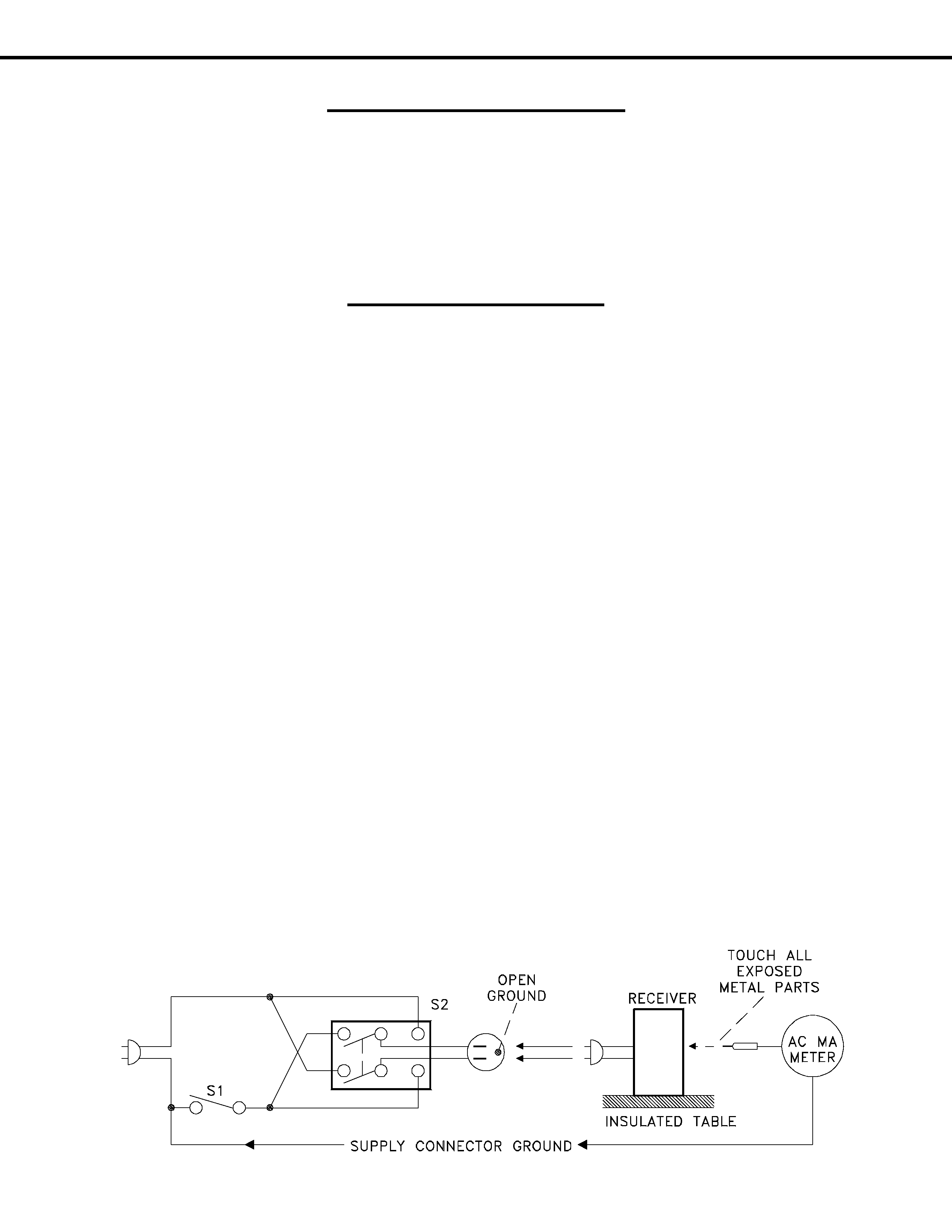
2. Hot Check ...Use the circuit shown below to perform the hot check test.
1. Keep switch S1 open and connect the receiver to the measuring circuit. Immediately after
connection, and with the switching devices of the receiver in their operating positions, measure
the leakage current for both positions of switch S2.
2. Close switch S1, energizing the receiver. Immediately after closing switch S1, and with the
switching devices of the receiver in their operating positions, measure the leakage current for both
positions of switch S2. Repeat the current measurements of items 1 and 2 after the receiver has
reached thermal stabilization. The leakage current must not exceed 0.5 milliampere (mA).

Reviews

There are no reviews of this manual yet.