MITSUBISHI DD6030 Service Manual

Cover page of MITSUBISHI DD6030 Service Manual

Service Manual for MITSUBISHI DD6030, downloadable as a PDF file.

Manual details

  • Immediate download after payment.
  • Delivered as a PDF file.
  • The manual has 90 pages
  • File size: 19.34 MB
  • Available language versions: English
  • Different language versions may vary sligthly in file size and page count.

We guarantee that...

  • our manuals are complete,
  • the manual includes circuit diagrams,
  • our manuals are checked with antivirus,
  • We'll issue refund if the manual is damaged, incomplete or unreadable (our refund policy)

Sample pages

Thumbnail of page 1Thumbnail of page 2Thumbnail of page 3Thumbnail of page 4
Thumbnail of page 5Thumbnail of page 6Thumbnail of page 7Thumbnail of page 8
Thumbnail of page 9
background image
MITSUBISHI DIGITAL ELECTRONICS AMERICA, INC.
9351 Jeronimo Rd. Irvine, CA 92618
Copyright © 2002 Mitsubishi Digital Electronics America, Inc.
All Rights Reserved
Operating conditions:
Temperature: 5°C to 35°C
Operation status:
Horizontal
Video output:
1.0 V (p-p), 75
, negative
sync., pin jack x 1
S Video output:
(Y) 1.0 V (p-p), 75
, nega-
tive sync., Mini DIN 4-pin x 1
(C) 0.286 V (p-p), 75
Component Video output: (Y) 1.0 V (p-p), 75
,
negative sync., pin jack x 1
(Cr, Pr)/(Cb, Pb) 0.7 V (p-p),
75
, pin jack x 2
Digital Audio output:
(Bitstream/PCM) 0.5 V (p-p),
75
, pin jack x 1,
Optical connector x 1
Analog Audio output:
2.0 V (rms), 680
, pin jack
2 CH L R x 2,
CAUTION
Before servicing this chassis, it is important that the service person reads all SAFETY PRECAUTIONS and the
SAFETY NOTICE in this manual.
SPECIFICATIONS
Power Supply:
120V AC, 60 Hz
Power Consumption:
17W
Weight:
5.5 lb.
External Dimensions:
17"x 2-3/4"x8-7/8"
(W/H/D)
Signal System:
Standard NTSC
Laser:
Semiconductor laser,
wavelength 650nm/780nm
Frequency Range:
(Digital Audio)
DVD Linear -
48 kHZ Sampling: 4 Hz to 22 kHz
96 kHZ Sampling: 4 Hz to 44 kHz
Signal-To-Noise Ratio:
More than 112 dB (EIAJ)
Audio Dynamic Range: More than 108 dB (EIAJ)
Harmonic Distortion:
Less than 0.002%
Wow and flutter:
Below measurable level
(less than ± 0.001%
(W.PEAK)) (EIAJ)
Service
Manual
2002
MITSUBISHELECTRIC
Model
DD-6030
DVD Player
background image
SAFETY NOTICE
SAFETY PRECAUTIONS
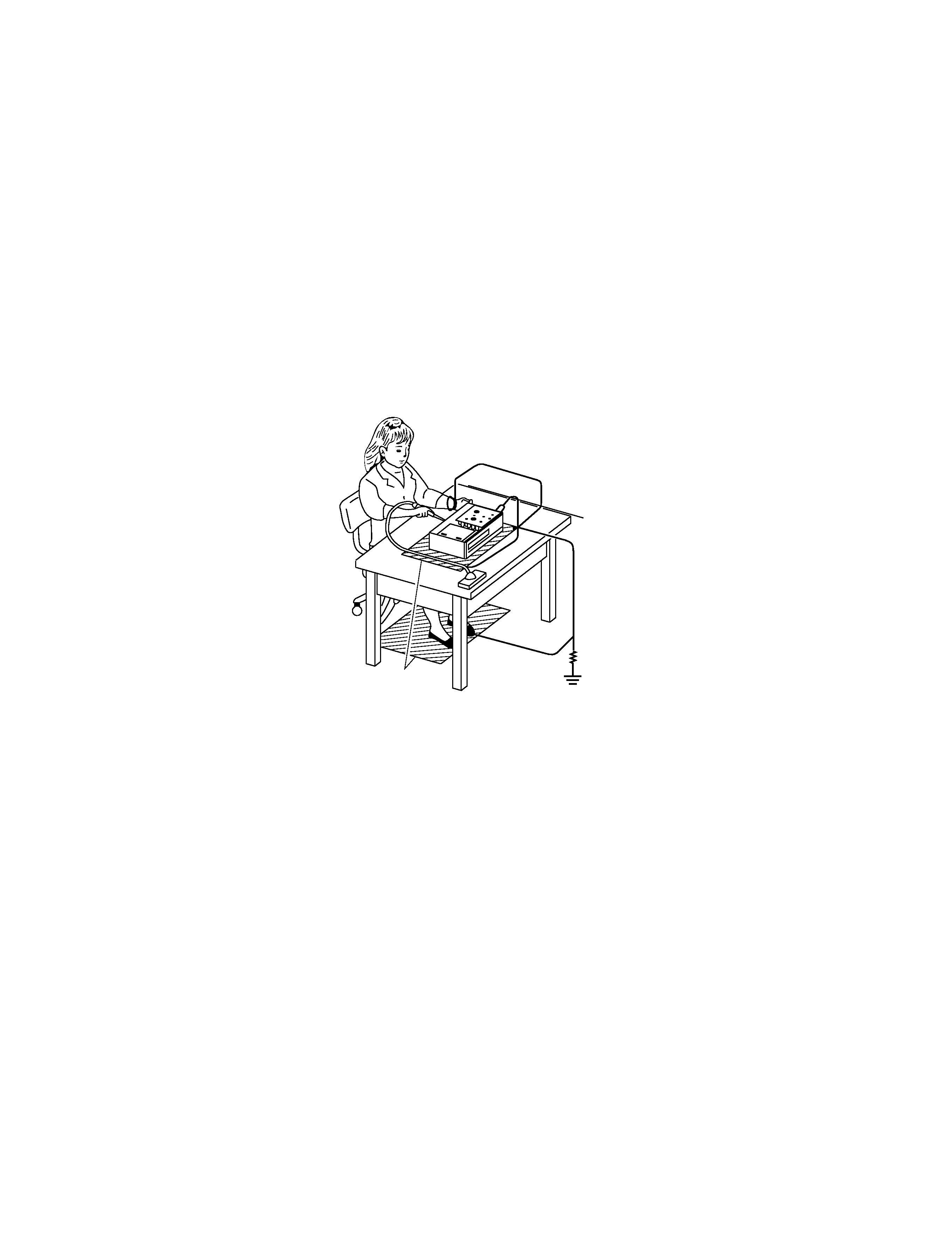
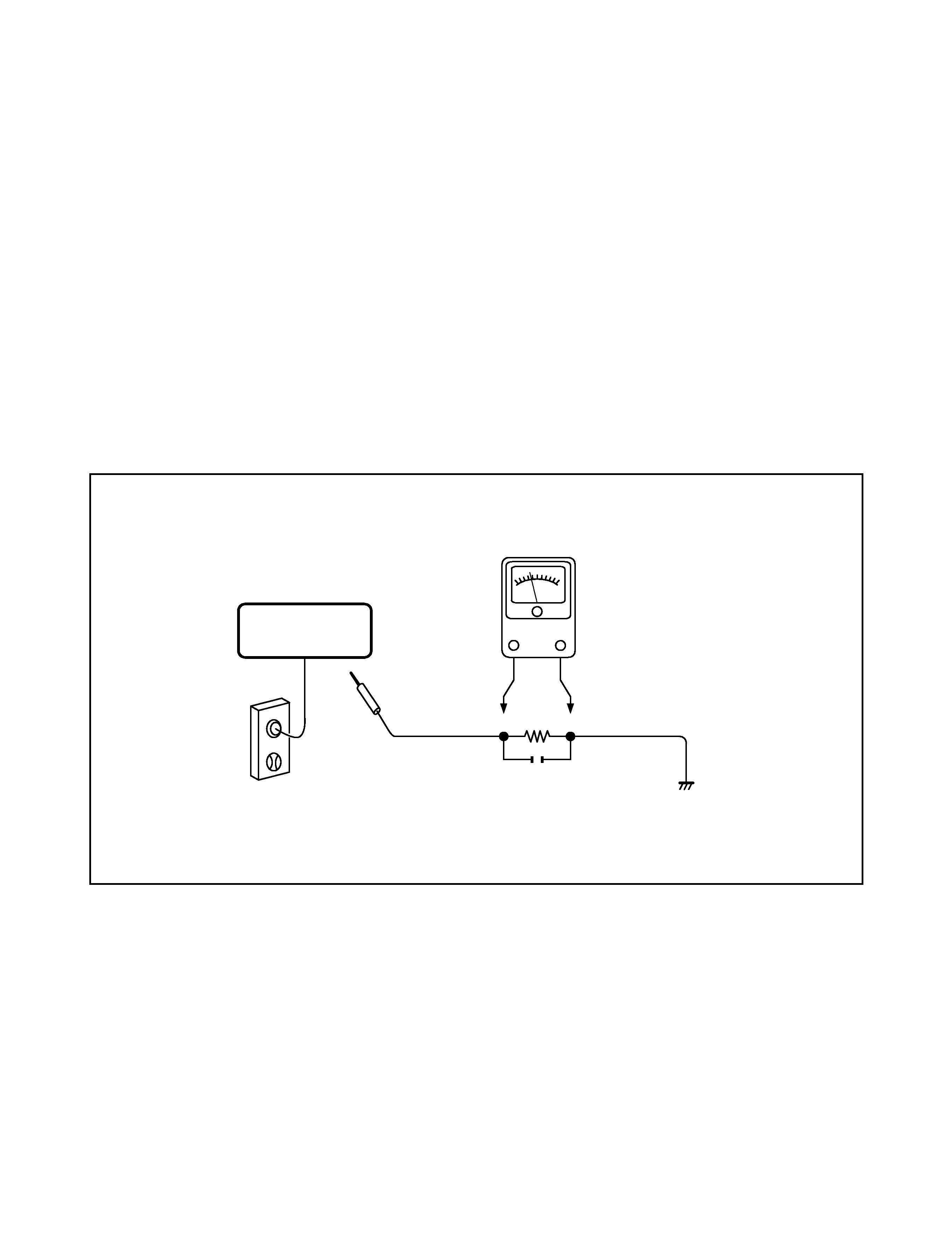
LEAKAGE CURRENT CHECK
Plug the AC line cord directly into a 120V AC outlet (do
not use an isolation transformer for this check). Use an
AC voltmeter, having 5000
per volt or more sensitivity.
Connect a 1500
10 W resistor, paralleled by a 0.15 µF
150V AC capacitor between a known good earth ground
(water pipe, conduit, etc.) and all exposed metal parts of
cabinet (antennas, handle bracket, metal cabinet
screwheads, metal overlays, control shafts, etc.).
Measure the AC voltage across the 1500
resistor.
The test must be conducted with the AC switch on and
then repeated with the AC switch off. The AC voltage
indicated by the meter may not exceed 0.3 V. A reading
exceeding 0.3 V indicates that a dangerous potential
exists, the fault must be located and corrected.
Repeat the above test with the DVD VIDEO PLAYER
power plug reversed.
NEVER RETURN A DVD VIDEO PLAYER TO THE
CUSTOMER WITHOUT TAKING NECESSARY
CORRECTIVE ACTION.
READING SHOULD NOT EXCEED 0.3V
DVD VIDEO PLAYER
AC VOLTMETER
(5000
9 per volt
or more sensitivity)
Good earth ground
such as a water pipe,
conduit, etc.
1500
9
10 W
0.15
µF 150V AC
AC OUTLET
Test all exposed metal.
Voltmeter Hook-up for Leakage Current Check
background image
LASER BEAM CAUTION LABEL
When the power supply is turned on, you may not remove this laser caution label. If it is removed, laser radiation
may be recceived.
The lightning flash with arrowhead symbol, within an
equilateral triangle, is intended to alert the user to the
presence of uninsulated "dangerous voltage" within the
product's enclosure that may be of sufficient magnitude to
constitute a risk of electric shock to persons.
The exclamation point within an equilateral triangle is
intended to alert the user to the presence of important
operating and maintenance (servicing) instructions in the
literature accompanying the appliance.
SAFETY NOTICE
background image
SECTION 1
GENERAL DESCRIPTIONS
SECTION
1
GENERAL
DESCRIPTIONS
1M
Ground conductive
wrist strap for body.
Soldering iron
with ground wire
or ceramic type
Conductive mat
The ground resistance
between the ground line
and the ground is less than 10
.
The Pickup Head consists of a laser diode that is very susceptible to external static electricity.
Although it may operate properly after replacement, if subjected to electrostatic discharge during replacement,
its life might be shortened. When replacing the laser diode, LSI's and IC's, use a conductive mat, soldering iron
with ground wire, etc. to protect against damage from static electricity.
1. PREPARATION FOR SERVICING
GENERAL
DESCRIPTIONS
1-1
background image
2. LOCATION OF MAIN PARTS AND MECHANISM PARTS
2-1. Location of Main Parts
Fig. 1-2-1
EU01 Main PC board
EU05 Output PC board
EU02 Power supply PC board
EU04 Power SW PC board
Loading motor PC board
Disc motor PC board
Feed motor PC board
EU03 Front display PC board

Reviews

There are no reviews of this manual yet.