MARANTZ PM11S1 Service Manual

Cover page of MARANTZ PM11S1 Service Manual

Service Manual for MARANTZ PM11S1, downloadable as a PDF file.

Manual details

  • Immediate download after payment.
  • Delivered as a PDF file.
  • The manual has 70 pages
  • File size: 5.57 MB
  • Available language versions: English
  • Different language versions may vary sligthly in file size and page count.

We guarantee that...

  • our manuals are complete,
  • the manual includes circuit diagrams,
  • our manuals are checked with antivirus,
  • We'll issue refund if the manual is damaged, incomplete or unreadable (our refund policy)

Sample pages

Thumbnail of page 1Thumbnail of page 2Thumbnail of page 3Thumbnail of page 4
Thumbnail of page 5Thumbnail of page 6Thumbnail of page 7Thumbnail of page 8
Thumbnail of page 9
background image
INTEGRARED AMPLIFIER PM-11S1
POWER ON/OFF
PHONES
VOLUME
A
TONE
SPEAKER
B
SPEAKER
REC OUT
PRE OUT
ATT.
MC
OPERATE
PHONO
DISPLAY
SELECTOR
INPUT
Integrated Amplifier
PM-11S1
Part no. 90M04AJ855010
First Issue 2004.07
ecm
Service
Manual
PM-11S1 /F1N /K1G /L1G /N1G /S1G
/N1S
Please use this service manual with referring to the user guide (D.F.U) without fail.
TABLE OF CONTENTS
SECTION
PAGE
1. TECHNICAL SPECIFICATIONS ........................................................................................... 1
2. CAUTION .............................................................................................................................. 1
3. ALIGNMENTS ...................................................................................................................... 2
4. SERVICE MODE / TRIM CHECK MODE (ENGLISH ) ......................................................... 4
5. MAIN MICROPROCESSOR (QU01) UPDATE PROCEDURE ........................................... 10
6. WIRING DIAGRAM ............................................................................................................. 25
7. BLOCK DIAGRAM .............................................................................................................. 26
8. SCHEMATIC DIAGRAM ..................................................................................................... 27
9. PARTS LOCATION ............................................................................................................. 32
10. IC DATA .............................................................................................................................. 37
11. EXPLODED VIEW AND PARTS LIST ................................................................................ 44
12. ELECTRICAL PARTS LIST ................................................................................................ 47
PM-11S1
background image
MARANTZ DESIGN AND SERVICE
Using superior design and selected high grade components,
MARANTZ company has created the ultimate in stereo sound.
Only original
MARANTZ parts can insure that your MARANTZ product will continue to perform to the specifications for which
it is famous.
Parts for your
MARANTZ equipment are generally available to our National Marantz Subsidiary or Agent.
ORDERING PARTS :
Parts can be ordered either by mail or by Fax.. In both cases, the correct part number has to be specified.
The following information must be supplied to eliminate delays in processing your order :
1. Complete address
2. Complete part numbers and quantities required
3. Description of parts
4. Model number for which part is required
5. Way of shipment
6. Signature : any order form or Fax. must be signed, otherwise such part order will be considered as null and void.
SHOCK, FIRE HAZARD SERVICE TEST :
CAUTION : After servicing this appliance and prior to returning to customer, measure the resistance between either primary AC
cord connector pins ( with unit NOT connected to AC mains and its Power switch ON ), and the face or Front Panel of product and
controls and chassis bottom.
Any resistance measurement less than 1 Megohms should cause unit to be repaired or corrected before AC power is applied, and
verified before it is return to the user/customer.
In case of difficulties, do not hesitate to contact the Technical
Department at above mentioned address.
040401ECM
SUPERSCOPE TECHNOLOGIES, INC.
USA
MARANTZ AMERICA, INC
1100 MAPLEWOOD DRIVE
ITASCA, IL. 60143
USA
PHONE : 630 - 741 - 0300
FAX
: 630 - 741 - 0301
JAPAN Technical
MARANTZ JAPAN, INC.
35- 1, 7- CHOME, SAGAMIONO
SAGAMIHARA - SHI, KANAGAWA
JAPAN 228-8505
PHONE : +81 42 748 1013
FAX
: +81 42 741 9190
EUROPE / TRADING
MARANTZ EUROPE B.V.
P. O. BOX 8744, BUILDING SILVERPOINT
BEEMDSTRAAT 11, 5653 MA EINDHOVEN
THE NETHERLANDS
PHONE : +31 - 40 - 2507844
FAX
: +31 - 40 - 2507860
AUSTRALIA
QualiFi Pty Ltd,
24 LIONEL ROAD,
MT. WAVERLEY VIC 3149
AUSTRALIA
PHONE : +61 - (0)3 - 9543 - 1522
FAX
: +61 - (0)3 - 9543 - 3677
NEW ZEALAND
WILDASH AUDIO SYSTEMS NZ
14 MALVERN ROAD MT ALBERT
AUCKLAND NEW ZEALAND
PHONE : +64 - 9 - 8451958
FAX
: +64 - 9 - 8463554
THAILAND
MRZ STANDARD CO., LTD
746 - 754 MAHACHAI ROAD.,
WANGBURAPAPIROM, PHRANAKORN,
BANGKOK, 10200 THAILAND
PHONE : +66 - 2 - 222 9181
FAX
: +66 - 2 - 224 6795
TAIWAN
PAI- YUING CO., LTD.
6 TH FL NO, 148 SUNG KIANG ROAD,
TAIPEI, 10429, TAIWAN R.O.C.
PHONE : +886 - 2 - 25221304
FAX
: +886 - 2 - 25630415
MALAYSIA
WO KEE HONG ELECTRONICS SDN. BHD.
2ND FLOOR BANGUNAN INFINITE CENTRE
LOT 1, JALAN 13/6, 46200 PETALING JAYA
SELANGOR DARUL EHSAN, MALAYSIA
PHONE : +60 - 3 - 7954 8088
FAX
: +60 - 3 - 7954 7088
AMERICAS
MARANTZ PROFESSIONAL PRODUCTS
2640 WHITE OAK CIRCLE, SUITE A
AURORA, ILLINOIS 60504 USA
PHONE : 630 - 820 - 4800
FAX
: 630 - 820 - 8103
KOREA
MK ENTERPRISES LTD.
ROOM 604/605, ELECTRO-OFFICETEL, 16-58,
3GA, HANGANG-RO, YONGSAN-KU, SEOUL
KOREA
PHONE : +822 - 3232 - 155
FAX
: +822 - 3232 - 154
SINGAPORE
WO KEE HONG DISTRIBUTION PTE LTD
No.1 JALAN KILANG TIMOR
#08-03 PACIFIC TECH CENTRE
SINGAPORE 159303
PHONE : +65 6376 0338
FAX
: +65 6376 0166
HONG KONG
Jolly ProAudio Broadcast Engineering Ltd.
UNIT 2, 10F, WAH HUNG CENTRE,
41 HUNG TO ROAD, KWUN TONG, KLN.,
HONG KONG
PHONE : 852 - 21913660
FAX
: 852 - 21913990
CANADA
MARANTZ CANADA INC.
5-505 APPLE CREEK BLVD.
MARKHAM, ONTARIO L3R 5B1
CANADA
PHONE : 905 - 415 - 9292
FAX
: 905 - 475 - 4159
TECHNICAL AUDIO GROUP PTY, LTD
43-53 Bridge Rd.,
STANMORE NSW 2048
AUSTRALIA
PHONE : +61 - (0)2 - 9519 - 0900
FAX
: +61 - (0)2 - 9519 - 0600
AUSTRALIA
background image
1
1. TECHNICAL SPECIFICATIONS
Power output
(20 Hz ­ 20 kHz simultaneous drive of both channels)
......................................................... 100W x 2 (8
load)
200W x 2 (4
load)
Total frequency distortion
(20Hz ­ 20kHz simultaneous drive of both channels, 8
load)
.............................................................................. 0.01%
Output band width (8
load, 0.05%) .................. 5Hz ~50kHz
Frequency response (CD, 1W, 8
load) .. 5Hz ~ 120kHz±3dB
Dumping factor (8
load, 20Hz ­ 20kHz) ....................... 100
Input sensitivity/Input impedance
PHONO (MC) .............................................. 270
µV/100
PHONO (MM) ................................................. 3mV/47k
BALANCED ............................................... 240mV/20k
CD/LINE .................................................... 240mV/20k
Output voltage/Output impedance
PRE OUT ...................................................... 1.9 V/220
Maximum allowed PHONO input (1kHz)
MC .......................................................................... 12mV
MM ....................................................................... 130mV
RIAA deviation (20Hz ~ 20kHz) ............................
±0.5dB
S/N (IHF-A, 1W, 8
load)
PHONO (MC) ................................... 76dB (0.5mV input)
PHONO (MM) ...................................... 90dB (5mV input)
BALANCED ..................................... 95dB (500mV input)
CD/LINE .......................................... 96dB (500mV input)
Tone control
Bass (50Hz) .............................................................
±8dB
Treble (20kHz) .........................................................
±8dB
Power requirement ............................. AC 230V 50Hz [/S, /N]
AC 220V 50/60Hz [/K]
AC 110V 60Hz [/L]
Power consumption
(EN60065) .............................................................. 380W
(4
, 200W x 2 output) ............................................ 880W
Accessories
Remote controller .......................................................... 1
AAA batteries ................................................................ 2
Detachable AC power cable .......................................... 1
Maximum outer dimensions (Amp)
Width ................................................................... 440mm
Height .................................................................. 165mm
Depth ................................................................... 444mm
Weight (Amp) .............................................................. 26.0kg
2. CAUTION
The layout of this amplifier is well concerned for sound quality.
1. When screws and washers are removed, those parts must
be set to the same places.
2. When wires are removed, the wires must be installed in the
same roots, same places.
3. Do not hold the side panel (007D) to move the unit when
the unit is disassembled.
background image
2
Adjustment Procedure
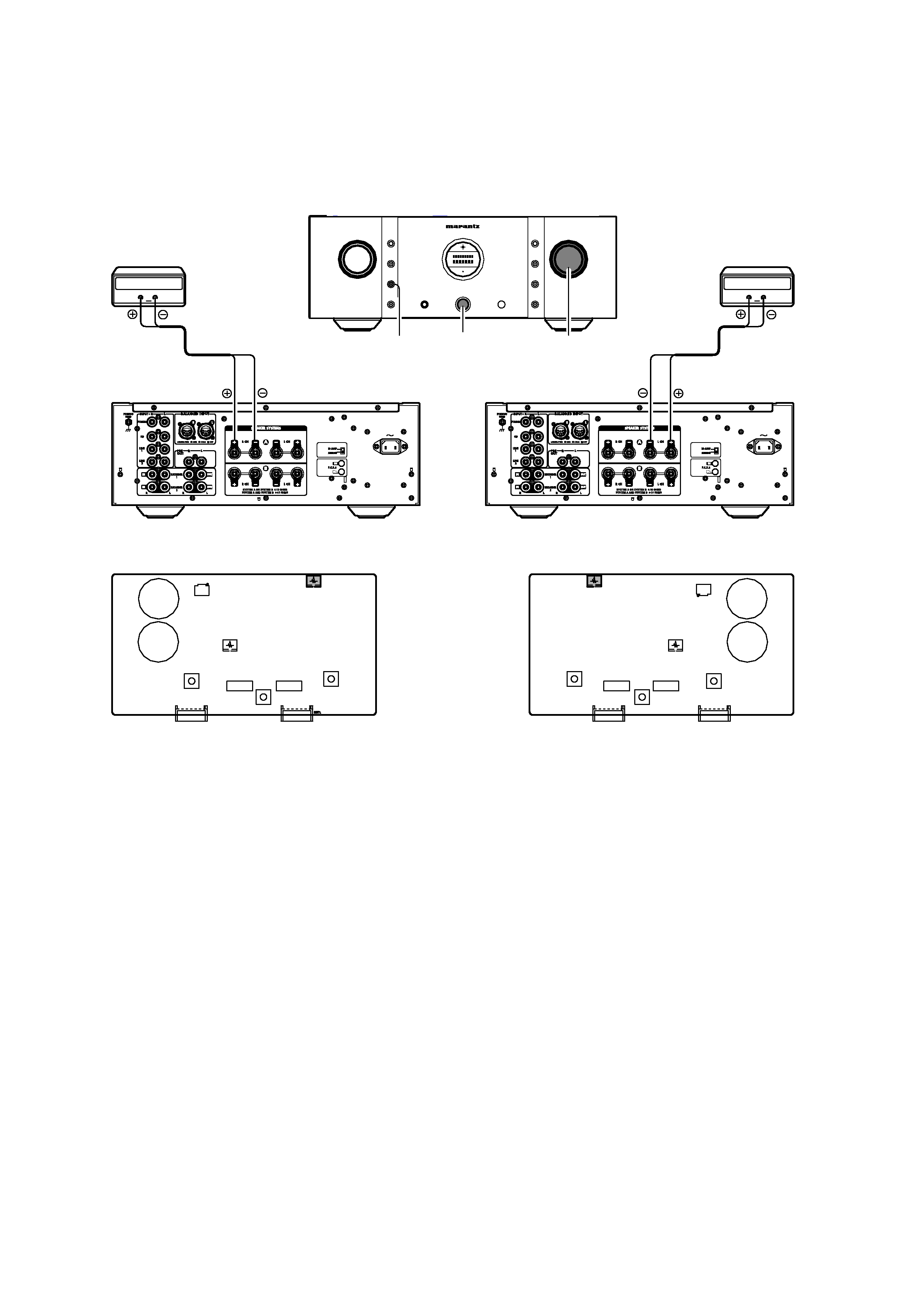
Set the power voltage to rated voltage for this adjustment
DC Offset Voltage Adjustment
3. ALIGNMENTS
1.
Before turning on the power,
Insert Digital Voltage Meter between the SPEAKER
SYSTEMS A (L CH) "+" and "­".
Insert Digital Voltage Meter between the SPEAKER
SYSTEMS R (R CH) "+" and "­".
2.
Turn on the power, VOLUME is set as
.
3.
Press the SPEAKER A button.
4.
After turn on the power and 2 minutes pass, first L CH is
adjusted.
The variable resistor R608 on P601 is turned with
adjustment driver, and the Digital Voltage Meter is adjusted
to "0mV±3mV".
5.
Then, R CH is adjusted.
The variable resistor R708 on P701 is turned with
adjustment driver, and the Digital Voltage Meter is adjusted
to "0mV±3mV".
P701(Rch)
P601(Lch)
R708
R608
AC IN
3
1
2
3
1
2
AC IN
3
1
2
3
1
2
Digital Voltmeter
R ch
Digital Voltmeter
L ch
INTEGRARED AMPLIFIER PM-11S1
POWER ON/OFF
POWER
ON/OFF
PHONES
VOLUME
A
TONE
SPEAKER
SPEAKER A
B
SPEAKER
REC OUT
PRE OUT
ATT.
MC
OPERATE
PHONO
DISPLAY
SELECTOR
INPUT
VOLUME
background image
3
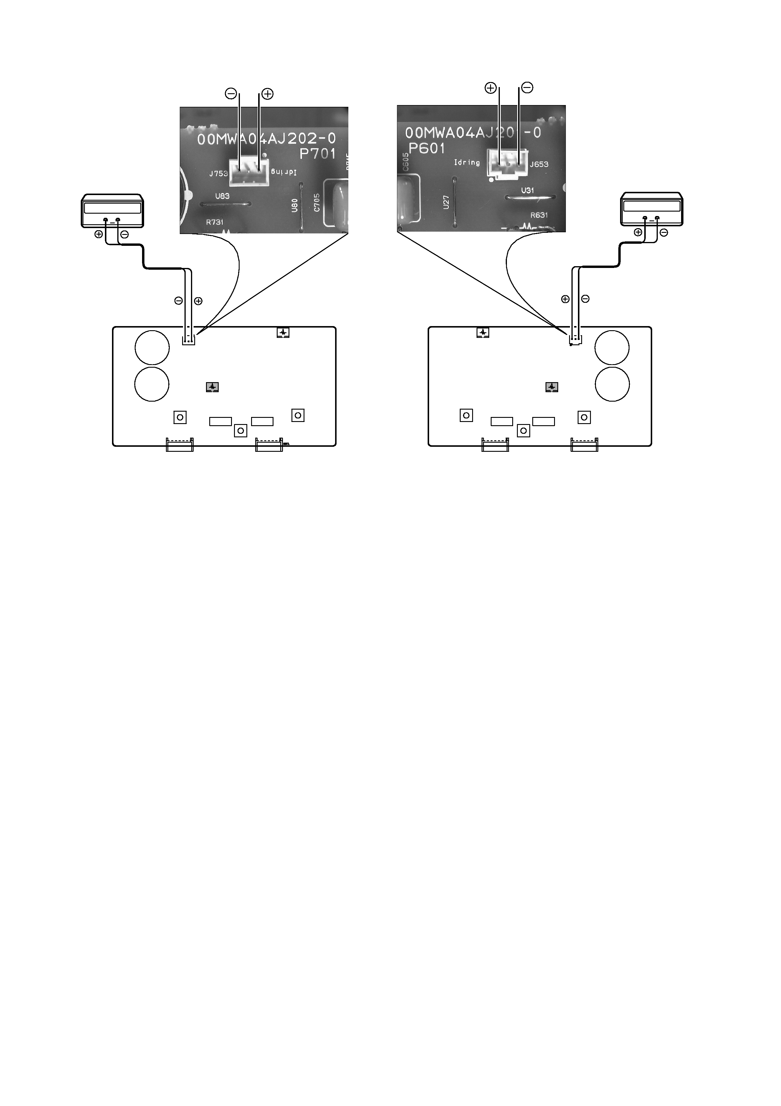
Idling Current Adjustment
1.
After DC Offset Voltage Adjustment is completed, adjust
the Idling Current with the variable resistor R619 and R719
on the PCB (P601/P701).
2.
Turn off the power.
3.
"+" of Connect Digital Voltage is connected to the No. 1
pin and connected "­" to No. 3 pin of J653.
4.
"+" of Connect Digital Voltage is connected to the No. 1
pin and connected "­" to No. 3 pin of J753.
5.
Before turning on the power, R619 and R719 have been
counter clockwise turned with the adjustment driver.
6.
Turn on the power, VOLUME is set as
.
7.
With seeing the digital voltage meter turn the variable
resister clockwise slowly to adjust the idling current.
· Idling adjustment with R619 (R719).
· Turn R619 (R719) clockwise to increase the idling current.
· The adjustment value of idling current is
11mV(55mA) ±0.5mV(2.5mA) each.
8. After 2 minutes, repeat the same procedure as 7.
· Turn R619 (R719) clockwise to increase the idling
current.
· The adjustment value of idling current is
11mV(55mA) ±0.5mV(2.5mA) each.
Adjustment is completed.
9. Remove connection cable, attach the top cover.
(Idling current decreases with the temperature rise inside the
unit, and it is set to 10mV (50mA) of setting value in about 30
minutes after turn on the power.)
P701
P601
R719
J753
R619
J653
Digital Voltmeter
R ch
Digital Voltmeter
L ch

Reviews

There are no reviews of this manual yet.