KENWOOD XDDV90 Service Manual

Cover page of KENWOOD XDDV90 Service Manual

Service Manual for KENWOOD XDDV90, downloadable as a PDF file.

We also have owner's manual to this model.

Manual details

  • Immediate download after payment.
  • Delivered as a PDF file.
  • The manual has 30 pages
  • File size: 4.16 MB
  • Available language versions: English
  • Different language versions may vary sligthly in file size and page count.

We guarantee that...

  • our manuals are complete,
  • the manual includes circuit diagrams,
  • our manuals are checked with antivirus,
  • We'll issue refund if the manual is damaged, incomplete or unreadable (our refund policy)

Sample pages

Thumbnail of page 1Thumbnail of page 2Thumbnail of page 3Thumbnail of page 4
Thumbnail of page 5Thumbnail of page 6Thumbnail of page 7Thumbnail of page 8
Thumbnail of page 9
background image
70%
MINI HiFi COMPONENT SYSTEM
RXD-DV90
SERVICE MANUAL
(XD-DV80/DV90)
© 2001-8 PRINTED IN KOREA
B51-5752-00 (K/K) 2312
* Refer to parts list on page 31 .
In compliance with Federal Regulations, following are repro-
duction of labels on, or inside the product relating to laser
product safety.
KENWOOD-Corp. certifies this equipment conforms to DHHS
Regulations No.21 CFR 1040. 10, Chapter 1, subchapter J.
DANGER : Laser radiation when open and interlock defeated.
AVOID DIRECT EXPOSURE TO BEAM.
EX.BASS
VOLUME
CONTROL
DISC SELECTOR
DISC SKIP
0OPEN/CLOSE
STANDBY
/TIMER
DISPLAY/DEMO
REVERSE MODE
VIDEO/AUX
POWER
DVD/CD
TAPE A
PHONES
MIC
MIC LEVEL
TAPE B
STOP
DOLBY DIGITAL
PRO LOGIC
TUNER
BAND
ON/STANDBY
LISTEN MODE
DVD
VCD
CD
SELECT
EN
TE
R
TUNING MODE
EQ MODE
/EX.BASS
SMART
MENU
M
U
LT
I
C
O
N
T
R
O
L
/P
.C
A
L
L
REC/ARM
4
¢
DISC 1
DISC 2
DISC 3
23
23
7
PUSH
OPEN
PUSH
OPEN
TAPE
A
PLAY
PLAY/REC TAPE
B
Door tray
(A22-1864-08))
Knob(MAIN)
(K29-8040-08)
Door deck(R)
(A52-0948-08)
Button(DISC)
(K29-8031-08)
Window *
(B10-)
Button(OPEN/CLOSE)
(K29-8037-08)
Button(MENU)
(K29-8039-08)
Button(REC/ARM)
(K29-8036-08)
Volume ring
(B01-2575-08)
Button(ON/STANDBY)
(K29-8038-08)
Door deck(L)
(A52-0947-08)
Front panel *
(A60-)
M and M2 types are available for MIC circuit.
background image
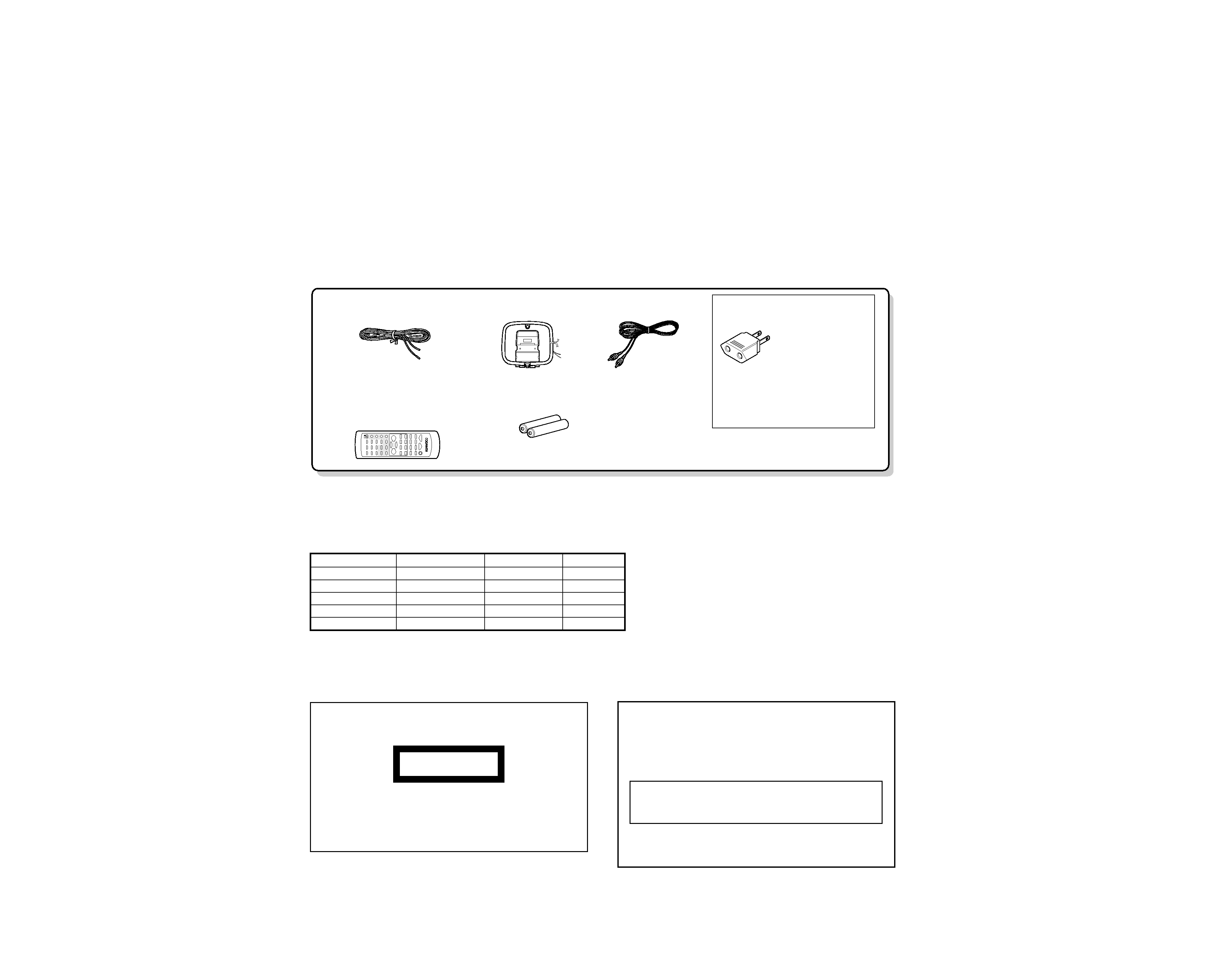
FM indoor antenna (1)
(T90-0881-08)
Loop antenna (1)
(T90-0882-08)
Remote control unit (1)
(A70-1533-08): DV90K....YX
(A70-1534-08):DV90E.....TE
(A70-1535-08): DV90M....MM2
Batteries (R6/AA) (2)
*AC plug adaptor (1)
(E03-0115-05)
* Use to adapt the plug on the
power cord to the shape of
the wall outlet.
(Accessory only for regions
where use is necessary.)
/
Video cord (1)
(E30-7235-08)
The marking is located on the rear panel and says that
the component uses laser beams that have been clas-
sified as Class 1. It means that the unit is utilizing laser
beams that are of a weaker class. There is no danger of
hazardous radiation outside the unit.
CLASS 1
LASER PRODUCT
The marking of products using lasers
(Except for some areas)
RXD-DV90
2
CONTENTS / ACCESSORIES / CAUTIONS
CONTENTS / ACCESSORIES / CAUTIONS ............. 2
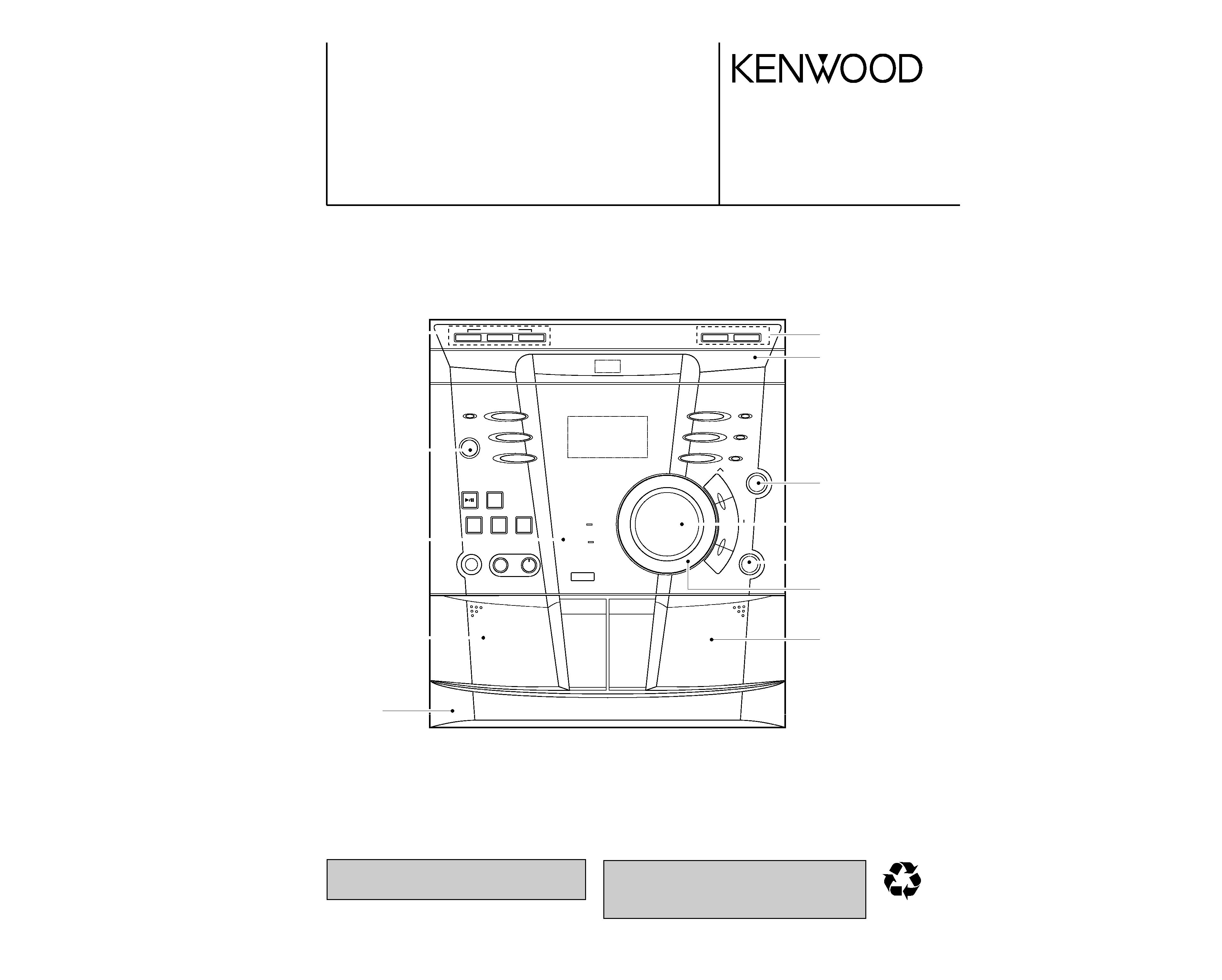
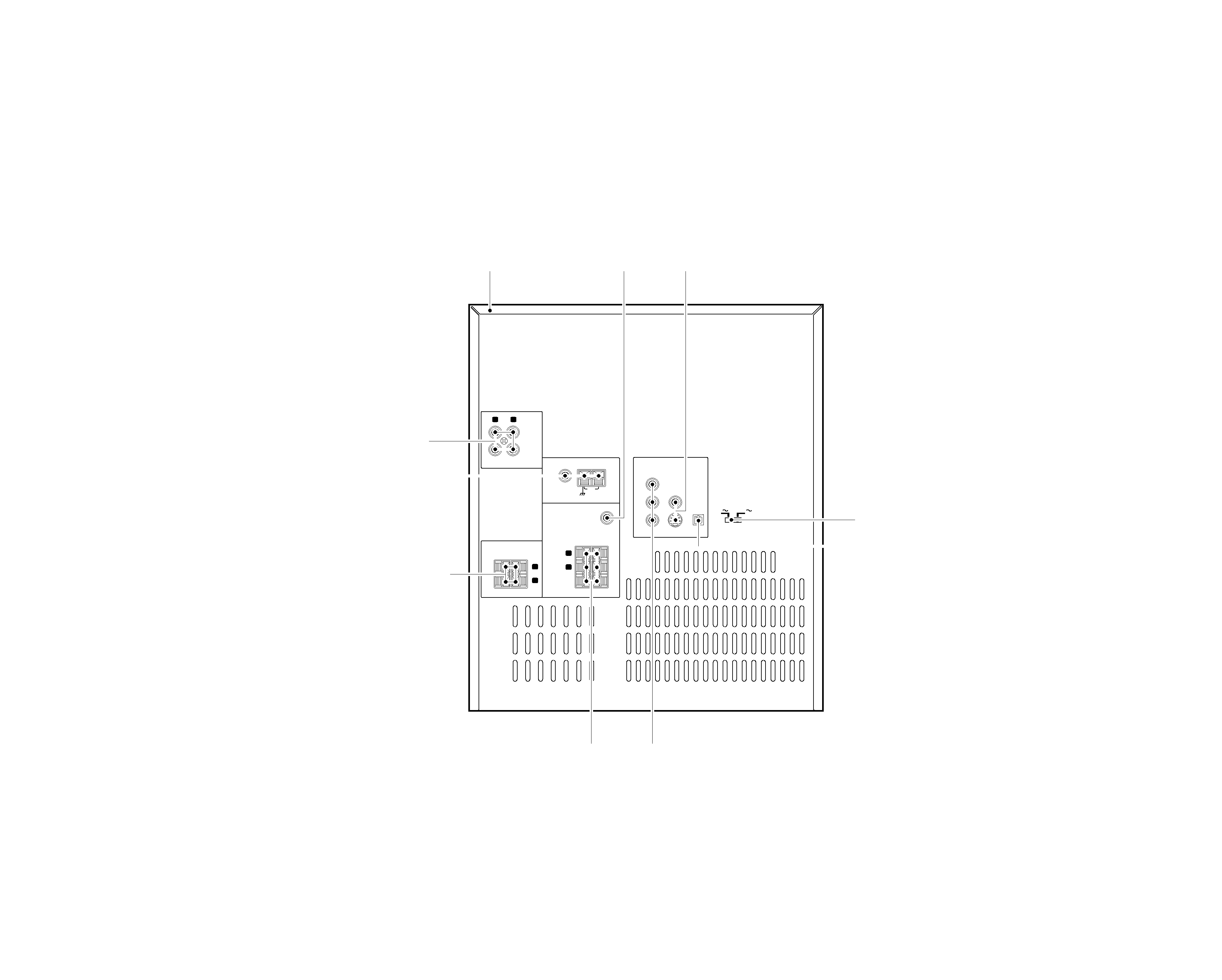
EXTERNAL VIEW .......................................................3
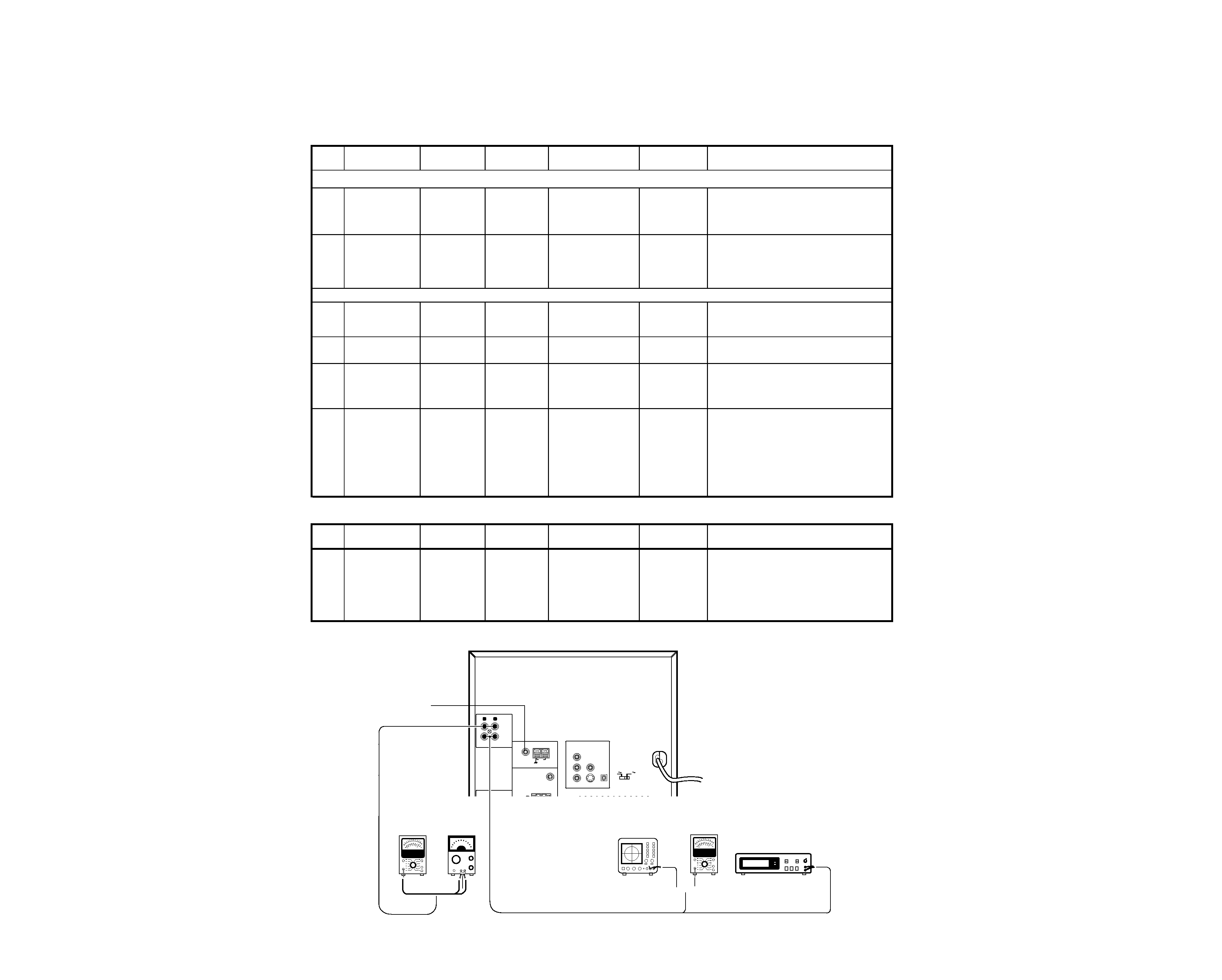
ADJUSTMENT ............................................................4
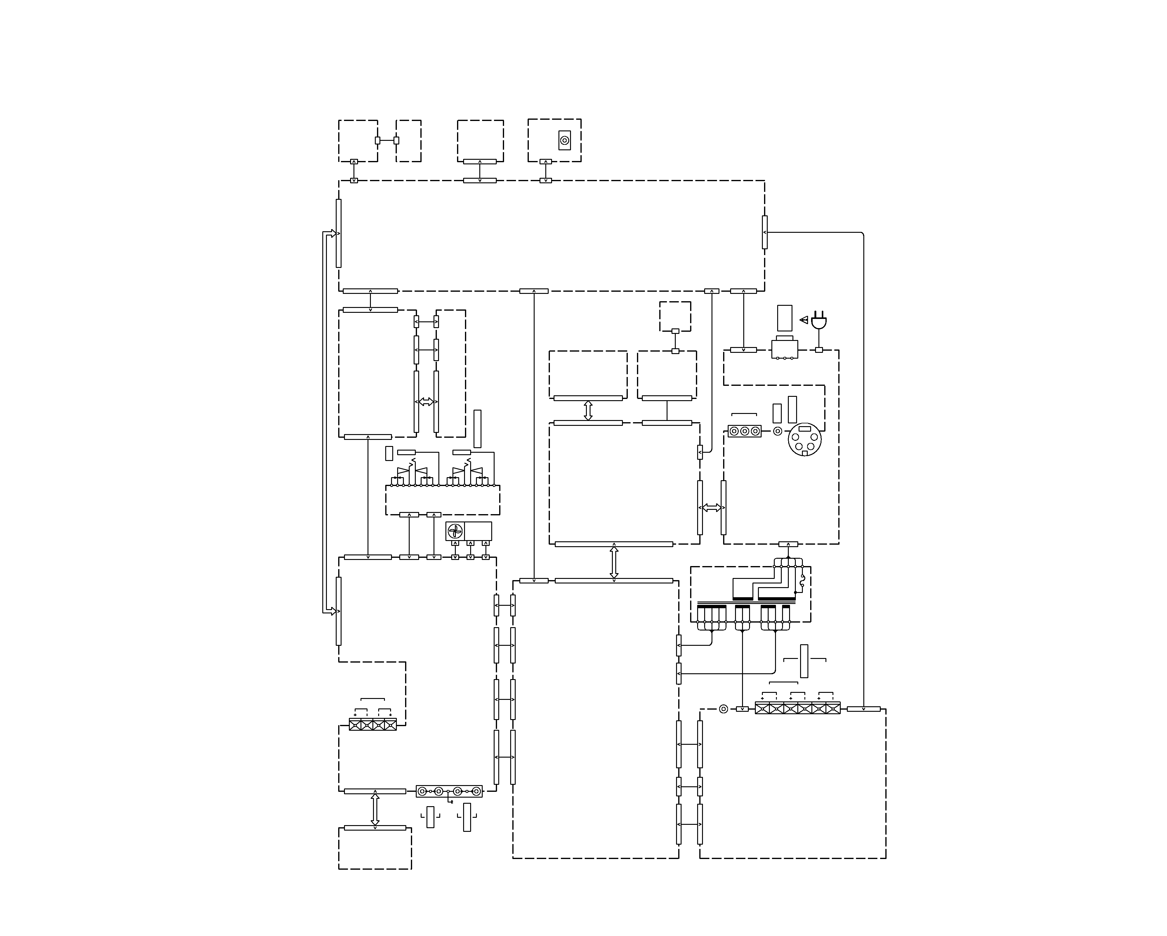
WIRING DIAGRAM .....................................................5
PC BOARD ................................................................ 6
SCHEMATIC DIAGRAM .......................................... 15
EXPLODED VIEW ....................................................29
PARTS LIST..............................................................31
SPECIFICATIONS ......................................Back cover
Contents
Accessories
SYSTEM
RECEIVER
SPEAKER
SPEAKER
XD-DV90
RXD-DV90
LS-N90V
CRS-N90V
XD-DV90(M2)
RXD-DV90(M2)
LS-N90V
CRS-N90V
XD-DV80
RXD-DV90
LS-N70V
CRS-N90V
XD-DV80(Y)
RXD-DV90
LS-N70V-H
CRS-N90V
XD-DV80(M2)
RXD-DV90(M2)
LS-N70V
CRS-N90V
Operation to reset
The microcomputer may fall into malfunction (impossibility to
operate, erroneous display, etc.) when the power cord is un-
plugged while power is ON or due to an external factor. In this
case, execute the following procedure to reset the microcom-
puter and return it to normal condition.
÷ Please note that resetting the microcomputer clears the
contents stored in and returns and to condition when it left
the factory.
Set the POWE key to ON. Then press the VIDEO/
down.
AUX key while holding the TUNING MODE key
System configurations
Cautions
background image
RXD-DV90
3
EXTERNAL VIEW
L
R
L
L
R
R
VIDEO/AUX
IN
OUT
FRONT SPEAKERS (6
)
SPEAKERS
S-VIDEO
FM 75
AM
GND
ANTENNA
SUB
WOOFER
PRE OUT
SURROUND
(8
)
COMPONENT
VIDEO OUTPUT
VIDEO
OUTPUT
DIGITAL
OUT
OPTICAL
CENTER
(6
)
AC 110-
120V
AC 220-
240V
Cr
Cb
Y
Cover(TOP)
(A52-0949-08)
DIN soket
(E63-1243-08)
Tuner ass'y *
(W02-)
Phono jack
(E63-1240-08)
Lock terminal board
(E70-0153-08)
Phono jack *
(E63-1242-08)
Digital out
(W02-2911-08)
Phono jack
(E63-1241-08)
Lock terminal board
(E70-0152-08)
Slide switch
(S62-0108-08)
* Refer to parts list on page 31 .
background image
RXD-DV90
4
ADJUSTMENT
L
R
L
L
R
R
VIDEO/AUX
IN
OUT
FRONT SPEAKERS (6
)
SPEAKERS
S-VIDEO
FM 75
AM
GND
ANTENNA
SUB
WOOFER
PRE OUT
SURROUND
(8
)
COMPONENT
VIDEO OUTPUT
VIDEO
OUTPUT
DIGITAL
OUT
OPTICAL
CENTER
(6
)
AC 110-
120V
AC 220-
240V
Cr
Cb
Y
Oscilloscope
FM SG
AUX IN
AUX OUT
AC voltmeter
Frequency counter
AC voltmeter
AG
{
(A)
(B)
Measurement Equipment Connections
CASSETTE DECK SECTION
INPUT
OUTPUT
CASSETE TAPE
ALIGNMENT
ALIGN FOR
SETTINGS
SETTINGS
DECK SETTINGS
POINT
0dB = 400mV
1. Cassette mechanism section (REC/PB head adjustment)
Power OFF
REC/PB head, Demagnetize the REC/PB head by head
Demagnetization
demagnetization,
erase head.
eraser.Clean the REC/PB head,erase
and cleaning
cleaning play
capstan,pinch head capstan and pinch roller with a
roller
cotton awab immersed in alcohol.
Adjust the output to maximum and
azimuth
MTT-114
Azimuth
adjust the azimuth adjustment screw
REC/PB Head
TCC-153
adjustment
for the Lissajours waveform pattern of
azimuth
10KHz,-10dB
screw
the oscilloscope to become close to a
45' straight line.
2.PC board adjustment
MTT-111
Adjust the tape speed so that 3kHz is
[1]
Tape speed
TCC-100
AUX OUTPUT
PLAY
VR901
obtained at the center of the tape.
3KHz, -4dB
(Frequency of 3KHZ +/- 40Hz)
[2]
PLAY BACK
MTT-130
AUX OUTPUT
PLAY
­
Playback output to 400mV +/- 50mV
LEVEL
CN902 Pin1 and Pin2(GND)
[3]
REC BIAS
REC/PB
AUX OUTPUT
REC
T901
Ensure that the Frequency Counter
Frequency
TEST TAPE
Adjust T901 to obtain this of 105KHz
AC-224
+/- 5KHz
Record 400Hz and 10.0kHz alternately,
REC/PB
and adjust the bias current adjustment
1.TP1(+) and TP2(GND)
REC BIAS
TEST TAPE
VR903(L)
Adjust VR903(L-CH) to obtain this of 3.5mV
[4]
Current
AC-224
AUX OUTPUT
REC/PLAY
2.TP3(+) and TP4(GND)
VR904(R)
Adjust VR904(R-CH) to obtain this of 3.5mV
AUX IN: 50mV
* potentiometer for the playback levels to
400Hz
become the same. (Spec.: +/-5dB)
AMPLIFIER SECTION
INPUT
OUTPUT
AMPLIFIER
ALIGNMENT
NO
ITEM
SETTING
SETTING
SETTING
POINT
ALIGN FOR
1.R234 Side Pin1 and Pin3
IDLE
NO SIGNAL
AUX
VR201(L)
Adjust VR201 to obtain this of +8 mV
[1]
CURRENT
VR(Min.)
­
FUNCTION
VR202(R)
1.R301 Side Pin1 and Pin3
Adjust VR202 to obtain this of +8 mV
(Spec.: +8mV +/-3mV)
# Idle Current: 20mA
NO
ITEM
PLAY
[1]
[2]
AUX OUTPUT
(B)
(B)
(B)
(B)
(B)
(A)
­
­
background image
RXD-DV90
5
17
119
1
1
13
1
5
17
1
1
15
1
11
1
10
1
6
CC402(15P)
CC401/
FPC
2
1
2
1
1
2
1
4
1
5
1
4
1
5
1
13
18
17
1
13
117
6
1
1
3
15
1
: AC240V~ 50Hz
: AC230V~ 50Hz
(X)
(T,E)
: AC110-120V/220-240V~
50/60Hz
(Y,M)
VCC
GND
OUT
1
2
3
33
1
15
1
11
1
1
10
6
1
11
1
13
1
51
11
1
5
1
13
1
5
1
3
1
15
33
1
1
41
1
19
14
11
1
14
19
2
1
1
5
15
1
15
2
1
1
1
7
4
1
7
1
FPC
119
CC801
FPC
1
9
1
2
21
21
9
1
3
11
3
1
9
1
9
8
1
8
1
1
22
1
CP401
CP402
JK402
Rch
Lch
AUX OUT
JK202
JK201
CN611
CP205
CP204
CP202
CP403
CP404
CP350
CP351
CP352
CP203
CP405
CN201
CN209
CN908
CP906
FPC
CC901
CN902
CN901
CN905
CN904
CN903
CP907
CN608
CN610
CN612
J601
JK3
OPTICAL
OUTPUT
JK101
L
R
CENTER
REAR
SPEAKERS
JK102
CN604
CN603
CN602
CN616
CN606
CN605
CN614
CN618
CP104
CP618
CP102
CN607
CP609
CP1
CN4
CN3
CN1
CP2
P002
B08
Cb
Y
Cr
JK1
JK2
CVBS
CN702
CN703
CN705
CN907
CN808
JK4
CP704
CN801
CN805
CP804
CP811
CP808
CN809
CP809
CN811
CP807
CN807
CP103
CN803
CP613
CN806
JK203
R
L
AUX IN
Lch
Rch
FRONT
SPEAKERS
MIC
HEADPHONE
WOOFER
SUB
PRE OUT
S-VIDEO
OUTPUT
VIDEO
CP810
SECTION
TUNER
MAIN BOARD
HEAT
SINK
FAN
MIC AMP
DECK BOARD
DECK
MECHANISM
BOARD
POWER AMP
SURROUND
BOARD
MAIN-TRANS
DVD MECHANISM
SIGNAL
CONTROL
VIDEO BOARD
STANDBY-
FRONT BOARD
SECTION
CD SW
DISC SW
SECTION
REMOTE/LED
SECTION
SECTION
ENCODER VR
RXD-DV90
PACK
BOARD
BOARD
WIRING
DIAGRAM

Reviews

There are no reviews of this manual yet.