KENWOOD XD-252 Owner's Manual

Cover page of KENWOOD XD-252 Owner's Manual

Owner's Manual for KENWOOD XD-252, downloadable as a PDF file.

Manual details

  • Immediate download after payment.
  • Delivered as a PDF file.
  • The manual has 56 pages
  • File size: 2.74 MB
  • Available language versions: English
  • Different language versions may vary sligthly in file size and page count.

We guarantee that...

  • our manuals are complete,
  • our manuals are checked with antivirus,
  • We'll issue refund if the manual is damaged, incomplete or unreadable (our refund policy)

Sample pages

Thumbnail of page 1Thumbnail of page 2Thumbnail of page 3Thumbnail of page 4
Thumbnail of page 5Thumbnail of page 6Thumbnail of page 7Thumbnail of page 8
Thumbnail of page 9
background image
COMPACT HI-FI SYSTEM
XD-SERIES
XD-V858
XD-V757
XD-V555
XD-V252
INSTRUCTION MANUAL
KENWOOD CORPORATION
This instruction manual is for some models.Model availability and features
(functions) may differ depending on the country and sales area.
B60-5095-00 00 MA (M,I) KW 0101
TINSZ0718AWZZ
background image
2 EN
THE EXCLAMATION POINT WITHIN AN EQUILATERAL TRIANGLE IS INTENDED TO ALERT THE USER
TO THE PRESENCE OF IMPORTANT OPERATING AND MAINTENANCE (SERVICING) INSTRUCTIONS
IN THE LITERATURE ACCOMPANYING THE APPLIANCE.
THE LIGHTNING FLASH WITH ARROWHEAD SYMBOL, WITHIN AN EQUILATERAL TRIANGLE, IS IN-
TENDED TO ALERT THE USER TO THE PRESENCE OF UNINSULATED "DANGEROUS VOLTAGE" WITHIN
THE PRODUCT'S ENCLOSURE THAT MAY BE OF SUFFICIENT MAGNITUDE TO CONSTITUTE A RISK
OF ELECTRIC SHOCK TO PERSONS.
CAUTION: TO REDUCE THE RISK OF ELECTRIC SHOCK,
DO NOT REMOVE COVER (OR BACK). NO USER-
SERVICEABLE PARTS INSIDE. REFER SERVICING TO
QUALIFIED SERVICE PERSONNEL.
BEFORE APPLYING POWER
Caution : Read this page carefully to ensure safe operation.
The marking of products using lasers
(Except for some areas)
The marking is located on the rear panel and
says this product has been classified as Class
1. It means that there is no danger of hazard-
ous radiation outside the product
CLASS 1
LASER PRODUCT
SAFETY PRECAUTIONS
WARNING : TO PREVENT FIRE OR ELECTRIC SHOCK, DO NOT
EXPOSE THIS APPLIANCE TO RAIN OR MOISTURE.
*
AC voltage selection
The AC voltage selector switches on the rear
panel are set to the voltage that prevails in the
area to which the unit is shipped. Before con-
necting the power cord to your AC outlet, make
sure that the setting positions of these switches
match your line voltage. If not, they must be set
to your voltage in accordance with the following
direction.
Note: Our warranty does not cover damage
caused by excessive line voltage due to improper
setting of the AC voltage selector switch.
AC voltage selector switches
Move switch lever to match your line voltage
with a small screwdriver or other pointed tool.
(110V, 127V, 220V or 230V - 240V AC)
CAUTION
RISK OF ELECTRIC SHOCK
DO NOT OPEN
Units are designed for operation as follows.
China ............................................ AC 220 V only
Other countries ............ AC 110 / 127 / 220 / 230-
240 V switchable*
230V
I
240V
background image
3 EN
CONTENTS
ACCESSORIES
Page
BEFORE APPLYING POWER .......................... 2
SAFETY PRECAUTIONS ................................. 2
ACCESSORIES .................................................... 3
HANDLING OF DISCS AND TAPES ..................... 4
NAMES OF CONTROLS AND INDICATORS .... 5 - 7
PREPARATION FOR USE ..............................8 - 10
SETTING THE CLOCK .................................. 11 -12
CHANNEL SPACE SETTING .............................. 12
SOUND CONTROL ........................................... 13
COMPACT DISC OPERATION ..................... 14 - 18
RADIO OPERATION ................................... 19 - 21
TYPES OF DISCS WHICH CAN BE PLAYED ..... 22
BEFORE USING VIDEO CD ............................... 23
VIDEO CD OPERATION
(During PBC on mode) ............................... 24 - 25
Page
VIDEO CD OPERATION
(During PBC off mode) ............................... 26 - 34
KARAOKE PLAYBACK ................................ 35 - 36
MP3 OPERATION ...................................... 37 - 38
CASSETTE OPERATION .................................... 39
RECORDING (TAPE B only) ........................ 40 - 42
HOW TO USE THE BUILT-IN TIMER ............ 43 - 45
USING EXTERNAL UNITS ................................. 46
RESETTING THE MICROCOMPUTER ............... 47
TRANSPORTING THE UNIT ............................... 47
MAINTENANCE ................................................ 48
IN CASE OF DIFFICULTY ........................... 49 - 51
DISPLAY MESSAGE LIST .................................. 51
SPECIFICATIONS ....................................... 52 - 54
AM Loop Antenna
(1)
"AA" size battery (UM/
SUM-3, R6, HP-7 or similar)
(2)
Remote Control
(1)
FM Antenna
(1)
Video Cable
(1)
Use to adapt the plug on the
power cord to the shape of the
wall outlet.
(Accessory only for regions where
use is necessary.)
AC Plug Adaptor (1)
background image
4 EN
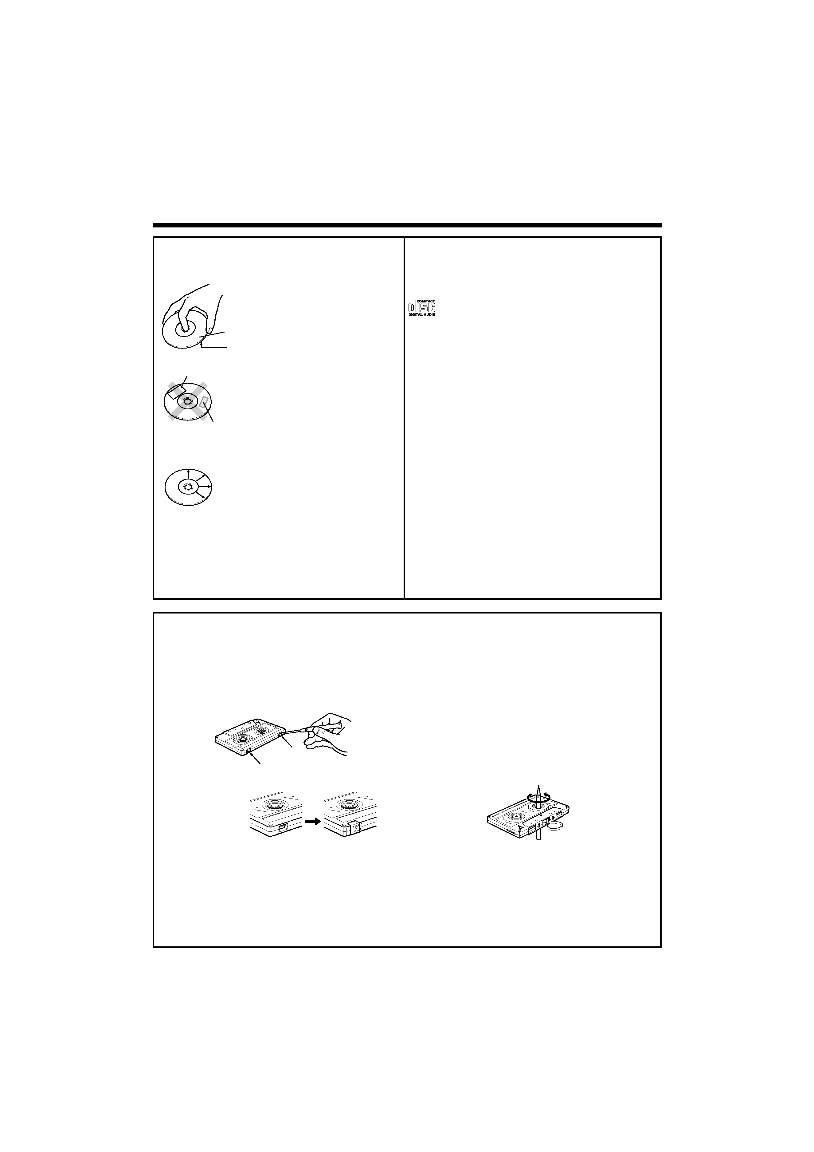
Disc handling precautions
Handling
Hold the discs so that you do not
touch the playing surface.
Do not attach paper or tape to ei-
ther the playing side or the label
side of the discs.
Cleaning
If fingerprints or foreign matter
become attached to the disc,
lightly wipe the disc with a soft
cotton cloth (or similar) from the
center of the disc outwards in a
radial manner.
Storage
When a disc is not to be played for a long period
of time, remove it from the player and store it in
its case.
Sticker
Sticky paste
HANDLING OF DISCS AND TAPES
Label side
Playing side
Discs which can be played with this unit
CD (12 cm, 8 cm), VCD and the audio part of CD-G,
CD-EG and CD-EXTRA. Use discs that comply with
the IEC standard, for example a disc carrying the
marking on the label surface.
Never play a cracked or warped disc
During playback, the disc rotates at high speed in
the player. Therefore, to avoid danger, never use a
cracked or deformed disc or a disc repaired with
tape or adhesive agent. Please do not use discs
which are not round because they may cause a
malfunction.
Disc accessories
The disc accessories (stabilizer, protection sheet,
protection ring, etc.) which are marketed for improv-
ing the sound quality or protecting discs as well as
the disc cleaner should not be used with this sys-
tem because they may cause malfunction.
Notes on cassette tape
Safety tab (accidental erasure preven-
tion tab)
After an important recording has been finished,
break the safety tab, to prevent the recorded con-
tents from being erased or recorded on accidentally.
To re-record
Apply tape only to the position where the tab has
been removed.
To store cassette tapes
Do not store the tapes in a place which is subject
to direct sunlight, or near equipment that gener-
ates heat. Keep the cassette tapes away from
any magnetic field.
When there is slack in the tape
In such a case, insert a pencil into the reel hole
and wind the reel hub to remove the slack.
For A side
For B side
Note :
· Do not use an endless tape, as this could damage the mechanism of the unit.
· Do not use a cassette with more than 90 minutes recording time, for the tape used in such a cassette
is very thin and tends to cause troubles such as engantlement around the pinch roller or cutting of
tape.
background image
5 EN
NAMES OF CONTROLS AND INDICATORS
FRONT PANEL
1 EX.BASS / DEMO button
2 STANDBY / TIMER indicator
3 REVERSE MODE button
4
ON / STANDBY button
5 VIDEO / AUX button
6 TAPE (A/B) button
7 TUNER (BAND) button
8 CD button
9 2 (Reverse play) button
0 7 STOP button
! 3 (Play / repeat) button
@ PHONES socket
# MIC socket
$ MIC LEVEL control
% PUSH OPEN (Tape A)
^ (TAPE A) Cassette compartment
& Display
* Disc tray
( DISC SKIP button
) 0 OPEN / CLOSE button
¡ SOUND MODE button
TM CLOCK button
£ TIMER button
¢ MEMORY / SET button
P. CALL (4 1 ¡ ¢) buttons
§ VOLUME CONTROL knob
¶ TUNING / TIME (%UP fiDOWN) buttons
· REC PAUSE button
ª MP3 indicator
º PUSH OPEN (Tape B)
/ (TAPE B) Cassette compartment
Standby mode
While the standby indicator of the unit is lit, a small amount of current is flowing into the unit's internal
circuitry to back up the memory. This condition is referred to as the standby mode of the unit. While
the unit is in the standby mode, it can be turned ON from the remote control unit.
º
/
ª

Reviews

There are no reviews of this manual yet.