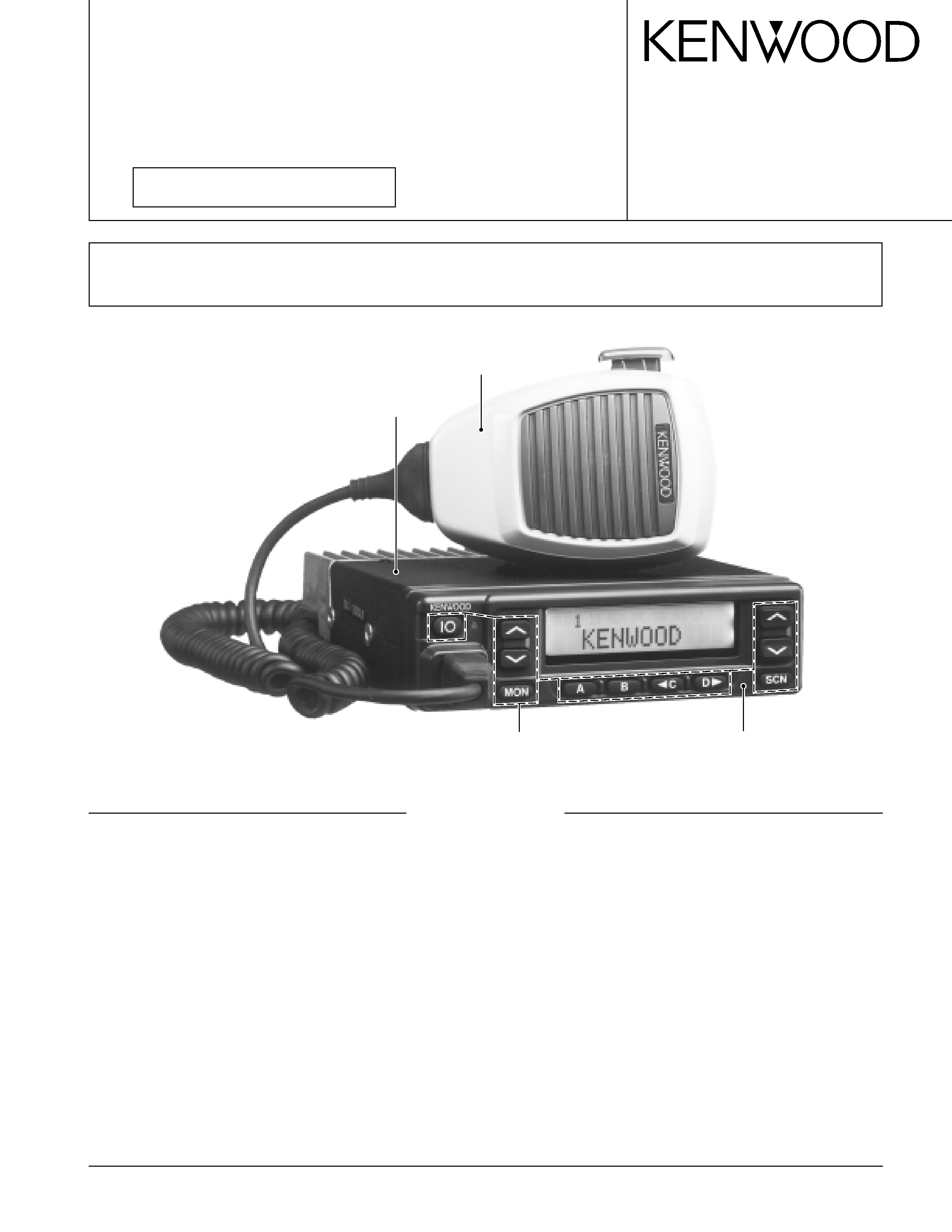
KENWOOD TK981 Service Manual

Cover page of KENWOOD TK981 Service Manual

Service Manual for KENWOOD TK981, downloadable as a PDF file.

We also have owner's manual to this model.

Manual details

  • Immediate download after payment.
  • Delivered as a PDF file.
  • The manual has 62 pages
  • File size: 3.95 MB
  • Available language versions: English
  • Different language versions may vary sligthly in file size and page count.

We guarantee that...

  • our manuals are complete,
  • the manual includes circuit diagrams,
  • our manuals are checked with antivirus,
  • We'll issue refund if the manual is damaged, incomplete or unreadable (our refund policy)

Sample pages

Thumbnail of page 1Thumbnail of page 2Thumbnail of page 3Thumbnail of page 4
Thumbnail of page 5Thumbnail of page 6Thumbnail of page 7Thumbnail of page 8
Thumbnail of page 9
background image
© 2001-9 PRINTED IN JAPAN
B51-8588-00 (N) 1016
800MHz/900MHz FM TRANSCEIVER
TK-980/981
SERVICE MANUAL
GENERAL ................................................................. 2
OPERATING FEATURES ......................................... 3
REALIGNMENT ...................................................... 13
INSTALLATION ...................................................... 16
CIRCUIT DESCRIPTION ......................................... 25
SEMICONDUCTOR DATA ..................................... 29
DESCRIPTION OF COMPONENTS ....................... 30
PARTS LIST ............................................................ 32
EXPLODED VIEW .................................................. 41
PACKING ................................................................ 42
ADJUSTMENT ....................................................... 43
PC BOARD VIEWS
PLL/VCO (X58-4530-XX) .................................. 50
TX-RX UNIT (X57-6520-XX) (A/2) ................... 51
TX-RX UNIT (X57-6520-XX) (B/2) .................... 57
SCHEMATIC DIAGRAM ........................................ 61
BLOCK DIAGRAM .................................................. 69
LEVEL DIAGRAM................................................... 72
TERMINAL FUNCTION ......................................... 74
SPECIFICATIONS................................................... 75
CONTENTS
Microphone
(T91-0621-05)
Cabinet (Upper)
(A01-2165-23)
Panel assy
(A62-0991-03)
Key top
(K29-5284-02)
SUPPLEMENT
This service manual applied to products with 30600001 or subsequent serial numbers.
In terms of the products with the serial numbers earlier than 30600001, refer to the TK-980/981 service manual as per
part No. B51-8478-10.
background image
2
TK-980/981
GENERAL
INTRODUCTION
SCOPE OF THIS MANUAL
This manual is intended for use by experienced techni-
cians familiar with similar types of commercial grade com-
munications equipment. It contains all required service in-
formation for the equipment and is current as of the publica-
tion date. Changes which may occur after publication are
covered by either Service Bulletins or Manual Revisions,
which are issued as required.
ORDERING REPLACEMENT PARTS
When ordering replacement parts or equipment informa-
tion, the full part identification number should be included.
This applies to all parts : components, kits, and chassis. If
the part number is not known, include the chassis or kit
number of which it is a part, and a sufficient description of
the required component for proper identification.
PERSONNEL SAFETY
The following precautions are recommended for person-
nel safety :
· DO NOT transmit if someone is within two feet (0.6
meter) of the antenna.
· DO NOT transmit until all RF connectors are secure and
any open connectors are properly terminated.
· SHUT OFF and DO NOT operate this equipment near
electrical blasting caps or in an explosive atmosphere.
· All equipment should be properly grounded before
power-up for safe operation.
· This equipment should be serviced by only qualified
technicians.
PRE-INSTALLATION CONSIDERNATIONS
1. UNPACKING
Unpack the radio from its shipping container and check
for accessory items. If any item is missing, please contact
KENWOOD immediately.
2. LICENSING REQUIREMENTS
Federal regulations require a station license for each ra-
dio installation (mobile or base) be obtained by the equip-
ment owner. The licensee is responsible for ensuring trans-
mitter power, frequency, and deviation are within the limits
permitted by the station license.
Transmitter adjustments may be performed only by a li-
censed technician holding an FCC first, second or general
class commercial radiotelephone operator's license. There
is no license required to install or operate the radio.
3. PRE-INSTALLATION CHECKOUT
3-1. Introduction
Each radio is adjusted and tested before shipment. How-
ever, it is recommended that receiver and transmitter op-
eration be checked for proper operation before installation.
3-2. Testing
The radio should be tested complete with all cabling and
accessories as they will be connected in the final installa-
tion. Transmitter frequency, deviation, and power output
should be checked, as should receiver sensitivity, squelch
operation, and audio output. QT equipment operation
should be verified.
4. PLANNING THE INSTALLATION
4-1. General
Inspect the vehicle and determine how and where the
radio antenna and accessories will be mounted.
Plan cable runs for protection against pinching or crush-
ing wiring, and radio installation to prevent overheating.
4-2. Antenna
The favored location for an antenna is in the center of a
large, flat conductive area, usually at the roof center. The
trunk lid is preferred, bond the trunk lid and vehicle chassis
using ground straps to ensure the lid is at chassis ground.
4-3. Radio
The universal mount bracket allows the radio to be
mounted in a variety of ways. Be sure the mounting surface
is adequate to support the radio's weight. Allow sufficient
space around the radio for air cooling. Position the radio
close enough to the vehicle operator to permit easy access
to the controls when driving.
4-4. DC Power and wiring
1. This radio may be installed in negative ground electrical
systems only. Reverse polarity will cause the cable fuse
to blow. Check the vehicle ground polarity before installa-
tion to prevent wasted time and effort.
2. Connect the positive power lead directly to the vehicle
battery positive terminal. Connecting the Positive lead to
any other positive voltage source in the vehicle is not rec-
ommended.
CAUTION
If DC power is to be controlled by the vehicle ignition
switch, a switching relay should be used to switch the posi-
tive power lead. The vehicle ignition switch then controls
DC to the relay coil.
3. Connect the ground lead directly to the battery negative
terminal.
4. The cable provided with the radio is sufficient to handle
the maximum radio current demand. If the cable must be
extended, be sure the additional wire is sufficient for the
current to be carried and length of the added lead.
background image
3
TK-980/981
1
3
+
­
7
6
13
15
5. INSTALLATION PLANNING ­ CONTROL STATIONS
5-1. Antenna system
Control station. The antenna system selection depends
on many factors and is beyond the scope of this manual.
Your KENWOOD dealer can help you select an antenna sys-
tem that will best serve your particular needs.
5-2. Radio location
Select a convenient location for your control station radio
which is as close as practical to the antenna cable entry
point. Secondly, use your system's power supply (which
supplies the voltage and current required for your system).
Make sure sufficient air can flow around the radio and power
supply to allow adequate cooling.
SERVICE
This radio is designed for easy servicing. Refer to the
schematic diagrams, printed circuit board views, and align-
ment procedures contained in this manual.
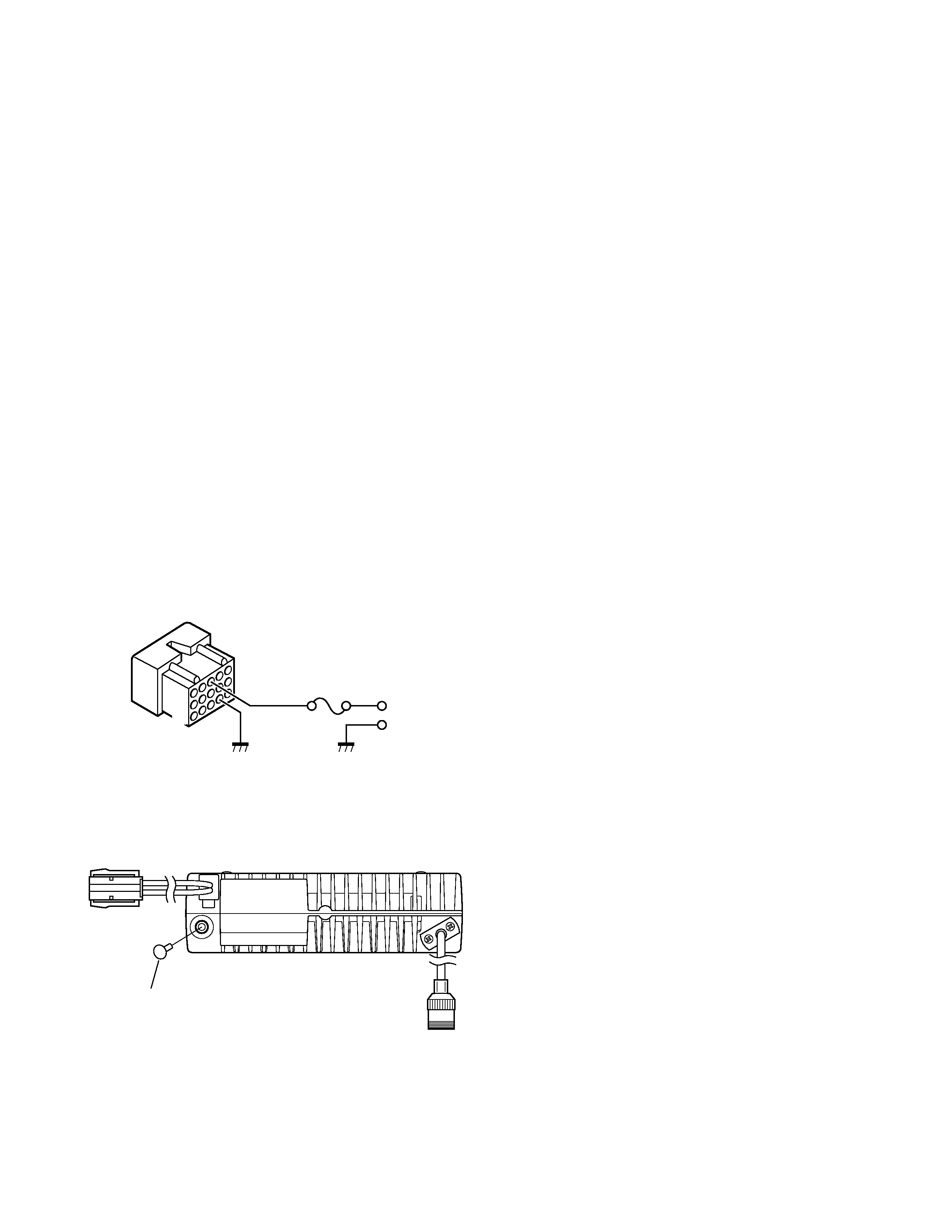
Note
When you modify your radio as described in system set-
up, take the following precaution.
The rating of pin 7 (SB) of the accessory connector cable
(KCT-19) on the rear of the radio is 13.6V (1A). Insert a 1A
fuse if you use the SB pin for external equipment.
Accessory connector
cable (KCT-19)
If you do not intend to use the 3.5-mm jack for the exter-
nal speaker, fit the supplied speaker-jack cap (B09-0235-05)
to stop dust and sand getting in.
GENERAL / OPERATING FEATURES
Speaker-jack cap
(B09-0235-05)
1. Operation Features
The TK-980/981 is an 800MHz/900MHz band EFJ LTRTM -
compatible trunked radio designed to operate in both
trunking and conventional modes. The programmable fea-
tures are summarized.
This model can handle up to 32 systems with up to 250
groups in each system. The transceiver can be used in both
trunked mode and conventional mode. Systems, groups,
and their functions are programmed.
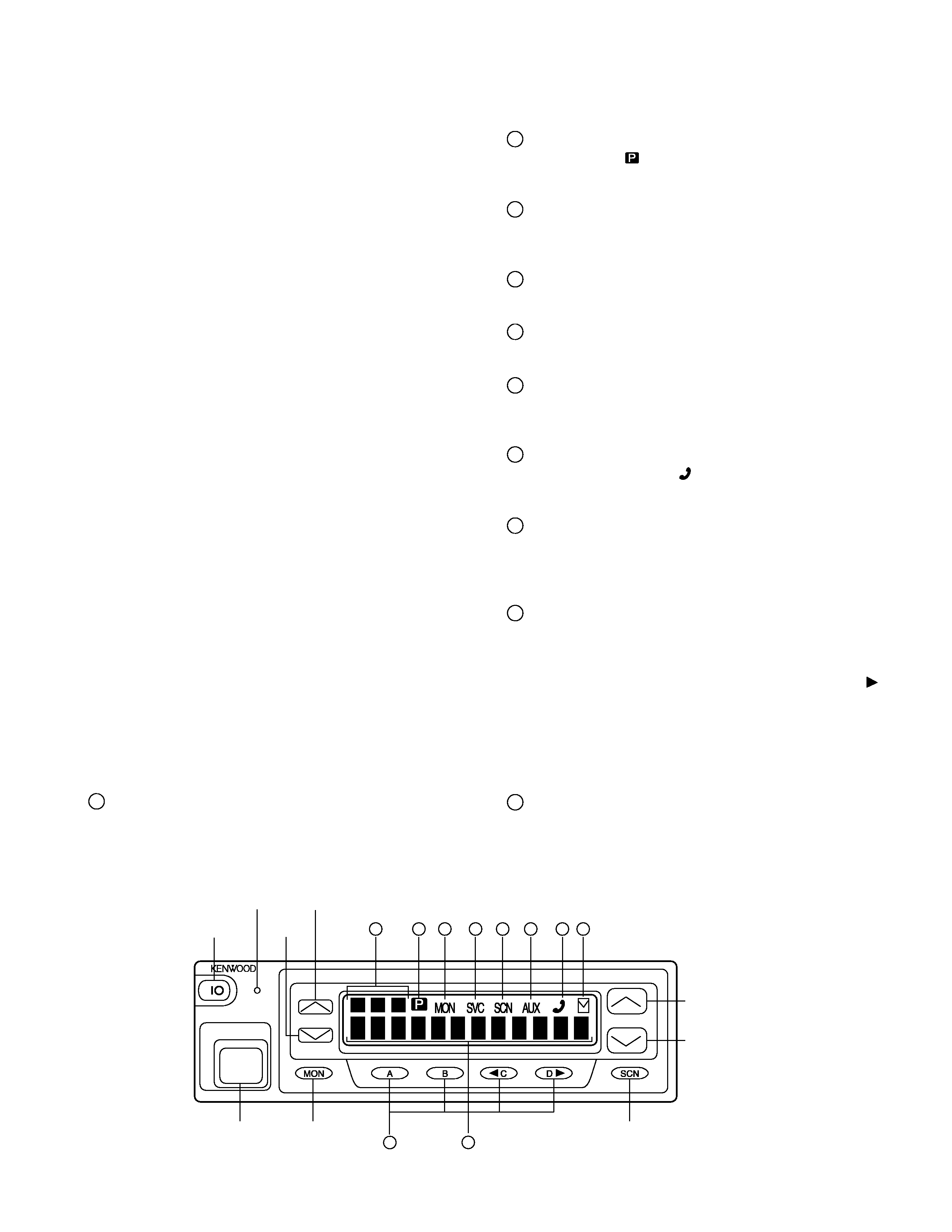
2. Transceiver Controls and Indicators (Fig. 1)
2-1. Front Panel Controls
All the keys on the front panel are momentary-type push
buttons. The functions of these keys are explained below.
· POWER key
Transceiver POWER key. When the power is switched
off, all the parameters, such as the system and group are
stored in memory. When the power is switched on again,
the transceiver returns to the previous conditions.
· SYSTEM UP/DOWN key (Programmable)
· SCAN key (Programmable)
· MONITOR key (Programmable)
· A, B, C and D key (Programmable)
· VOLUME UP/DOWN key (Programmable)
· BUSY/TX LED
The BUSY indicator (Green LED) shows that the group is
in use. The TX indicator (Red LED) shows that you are trans-
mitting.
2-2. Programmable Keys
The FPU (KPG-49D) enables programmable keys to se-
lect the following functions.
Auto tel, AUX-A, AUX-B (Only when voice scrambler is
not selected), DTMF ID (BOT), DTMF ID (EOT), Display char-
acter, Emergency (Only foot key), Function, Group down,
Group up, Home group, Horn alert, Key lock, Memory (RCL/
STO), Memory (RCL), Memory (STO), Message mode (Only
A key), Monitor A, Monitor B, Monitor C, Monitor D, Public
address, Redial, Scan, Scan del/add, Scan temporary delete,
Scrambler (Only when voice scrambler is selected), Send
GPS, System down, System up, TEL disconnect, Volume
down, Volume up and None.
These functions the FPU programs to the function keys
and described in the following sections.
· Auto TEL
Automatically connects available repeaters that are con-
nected to telephone circuits when operating as LTR system.
The time allocated to search for available repeaters is 60
seconds, after which connection failure occurs, a DTMF
tone is output and the function terminates.
If connection to an available circuit is made, only ID 253,
EOT or hang-up time-out can terminate the function.
background image
4
TK-980/981
· AUX-A
If this key is pressed, "AUX" icon lights on the LCD and
AUX port which is inside of the transceiver turns to the high
level. If pressed again, the "AUX" icon goes off and the
AUX ports turns to the lower level.
· AUX-B
This function can be programmed when the voice scram-
bler board is not installed.
If this key is pressed, an underscore ("_") appears at the
extreme right of the LCD and AUX port which is inside of the
transceiver turns to the active level. If pressed again, the
underscore disappears and the AUX ports turns to the
deactive level.
· DTMF ID (BOT)
In conventional mode, if you press this key, a predeter-
mined DTMF ID (Begin of TX) will be sent automatically.
· DTMF ID (EOT)
In conventional mode, if you press this key, a predeter-
mined DTMF ID (End of TX) will be automatically sent.
· Display character
This key switches the LCD display between the system
and group number and the system and group name.
· Emergency
Pressing this key for longer than the programmed "Emer-
gency Key Delay Time" causes the transceiver to enter the
emergency mode. The transceiver jumps to the pro-
grammed "Emergency system and group" and transmits for
the programmed "Active Time".
The transceiver disables mic mute while transmitting.
After finishing transmission, the transceiver receivers for
the programmed "Interval Time". The transceiver mutes
the speaker while receiving. Following the above sequence,
the transceiver continues to transmit and receive.
· Function
Pressing this key causes the transceiver to display
"FCN". Then, pressing a microphone DTMF key causes the
corresponding programmed function to start. This key may
be convenient when using many functions with the micro-
phone 12-key keypad.
· Group Up/Down
When the key is pressed each time, the group number to
be selected is incremented/decremented and repeats if held
for one second or longer.
· Home Group
Each pressing of the key selects a preset system/group.
OPERATING FEATURES
· Horn Alert
If you are called from the base station using DTMF while
you are away from your transceiver, you will be alerted by
the vehicle horn or some other type of external alert. To turn
the horn alert function on , press this key. A confirmation
tone sounds, and the display shows "HA" on the sub LCD.
If this key is pressed again, the horn alert function is
turned off.
· Key Lock
Pressing this key causes the transceiver to accept entry
of only the [Function], [Key lock], [PTT], [Monitor A], [Moni-
tor B], [Monitor C], [Monitor D], and [Emergency] keys.
· Message Mode
Press this key to enter the message mode. (See "Alpha-
numeric Two-way Paging Function" for details)
· Memory
This key allows DTMF memory data to be recalled; up to
32 memories each with a memory dial of up to 16 digits and
an A/N of up to 10 digits per memory.
· Monitor
Used to release signalling or squelch when operating as a
conventional. It is also used to reset option signalling.
· Public Address
Public address amplifies the microphone audio, and out-
puts it through a PA speaker. PA is activated by pressing
this key. A confirmation tone sounds, and the display
shows "PUBLIC ADRS". PA can be activated at anytime
(scanning or non-scanning).
The RADIO continues to scan & receive calls while in PA
mode. Pressing PTT activates PA, and will override an in-
coming call at anytime; however, no RADIO transmission
takes place.
If this key is pressed again, a confirmation tone will
sound, the display will return to the normal group or SCAN
display, and the PA function will turn off.
· Redial
If you press this key when the system/group is displayed,
the last transmitted DTMF code will appear on the display.
Pressing the PTT switch at this time will transmit the dis-
played DTMF code.
· Scan
Press this key starts scanning. Pressing this key stops
scanning.
· Scan Del/Add
Used to select whether system scan routines are used
during system scan. Each pressing of the key (to ON)
toggles between lockout and lock. The scan routine is
started when on lock. The DEL indicator flashes when the
system is on lockout.
background image
5
TK-980/981
· Scan Temporary Delete
This key is temporarily deleted a system being scanned.
If you press this key when scan is stopped (when a call is
being received from another station), the system is tempo-
rarily deleted and scanning restarts.
This key operates even when "Scan Type" is set to "List
Type System Scan".
· Scrambler
If a scrambler code (1 to 16) has been set in the FPU, an
underscore ("_") appears at the extreme right of the LCD
display when scrambler is active. Pressing this key changes
on/off of scramble operation. Press this key for 2 seconds
to enter scrambler code selection mode.
· Send GPS (Optional)
Pressing this key causes the transceiver to send a single
GPS data. (GPS receiver must be installed.)
· System Up/Down
When the key is pressed each time, the system number
to be selected is incremented/decremented and repeats if
held for one second or longer.
· Telephone Disconnect
Pressing this key ends an RIC connection (disconnects
the telephone line).
· Volume Up/Down
When the key is pressed, the volume level is increased/
decreased and repeats if held for 200ms or longer.
· None
Sounds error operation beep, and no action will occur.
Use this function when the transceiver is required to be
more simple operated.
2-3. Front Panel Displays and Indicators
Sub display
Displays the system and group numbers. Also displays
various functions, such as TA.
P (Priority) indicator
The P indicator (
) appears when a selected group is pro-
grammed as priority, in conventional operation.
MON (Monitor) indicator
The MON indicator appears when the button pro-
grammed as MONITOR is pressed.
SVC (Service) indictor
This icon is not used this transceiver.
SCN (Scan) indicator
The SCN indicator appears when using scan mode.
AUX (Auxiliary) indicator
appears when the auxiliary function is activated (ON) by
pressing the AUX-A key.
Handset indicator
The handset indicator ( ) appears when the selected
group is programmed as telephone IDs.
MAIL indicator
Flashes when a status message (FleetSyncTM) is re-
ceived. Lights when a status message is stored in the stack
memory.
Alphanumeric display
The twelve-character dot matrix alphanumeric display
shows the system/group numbers. You can program sys-
tem/group names with up to ten characters in place of these
numbers. The left display is used as a delete indicator (
)
and the right is used for the selective call (*) or scrambler
(_) function. The delete indicator shows the systems
locked out of the scanning sequence. Selective call and
scrambler are optional functions that can be programmed.
Displays received messages when using FleetSyncTM.
A,B,C,D key
These keys are programmable function (PF) keys.
OPERATING FEATURES
Fig. 1
MODULAR
MIC JACK
MONITOR
SCAN
POWER
BUSY/
TX LED
VOLUME
UP
VOLUME
DOWN
SYSTEM UP
SYSTEM DOWN
1
2
3
10
9
4
5
6
7
8
1
2
3
4
5
6
7
8
9
10

Reviews

There are no reviews of this manual yet.