KENWOOD TK863G Service Manual

Cover page of KENWOOD TK863G Service Manual

Service Manual for KENWOOD TK863G, downloadable as a PDF file.

We also have owner's manual to this model.

Manual details

  • Immediate download after payment.
  • Delivered as a PDF file.
  • The manual has 56 pages
  • File size: 3.57 MB
  • Available language versions: English
  • Different language versions may vary sligthly in file size and page count.

We guarantee that...

  • our manuals are complete,
  • the manual includes circuit diagrams,
  • our manuals are checked with antivirus,
  • We'll issue refund if the manual is damaged, incomplete or unreadable (our refund policy)

Sample pages

Thumbnail of page 1Thumbnail of page 2Thumbnail of page 3Thumbnail of page 4
Thumbnail of page 5Thumbnail of page 6Thumbnail of page 7Thumbnail of page 8
Thumbnail of page 9
background image
© 2002-1 PRINTED IN JAPAN
B51-8617-00 (N) 1231
UHF FM TRANSCEIVER
TK-863G
SERVICE MANUAL
GENERAL .................................................. 2
SYSTEM SET-UP ...................................... 2
OPERATING FEATURES .......................... 3
REALIGNMENT ......................................... 9
INSTALLATION ....................................... 12
CIRCUIT DESCRIPTION .......................... 18
SEMICONDUCTOR DATA ...................... 23
DESCRIPTION OF COMPONENTS ........ 24
PARTS LIST ............................................. 27
EXPLODED VIEW .................................... 34
PACKING ................................................. 35
ADJUSTMENT ........................................ 36
LEVEL DIAGRAM .................................... 45
PC BOARD VIEWS
DISPLAY UNIT (X54-3270-10) ............ 47
PLL/VCO (X58-4670-17) ...................... 48
TX-RX UNIT (X57-6490-10) (A/2) ....... 49
TX-RX UNIT (X57-6490-10) (B/2) ....... 55
SCHEMATIC DIAGRAM .......................... 59
BLOCK DIAGRAM ................................... 63
TERMINAL FUNCTION ........................... 66
SPECIFICATIONS .................................... 67
CONTENTS
Microphone
(T91-0621-05)
Cabinet (Upper)
(A01-2165-23)
Panel assy
(A62-0642-03)
Key top
(K29-9140-02)
background image
2
TK-863G
GENERAL / SYSTEM SET-UP
INTRODUCTION
SCOPE OF THIS MANUAL
This manual is intended for use by experienced techni-
cians familiar with similar types of commercial grade com-
munications equipment. It contains all required service in-
formation for the equipment and is current as of the publica-
tion date. Changes which may occur after publication are
covered by either Service Bulletins or Manual Revisions.
These are issued as required.
ORDERING REPLACEMENT PARTS
When ordering replacement parts or equipment informa-
tion, the full part identification number should be included.
This applies to all parts : components, kits, or chassis. If the
part number is not known, include the chassis or kit number
of which it is a part, and a sufficient description of the re-
quired component for proper identification.
PERSONNEL SAFETY
The following precautions are recommended for person-
nel safety :
· DO NOT transmit if someone is within two feet (0.6
meter) of the antenna.
· DO NOT transmit until all RF connectors are verified se-
cure and any open connectors are properly terminated.
· SHUT OFF and DO NOT operate this equipment near
electrical blasting caps or in an explosive atmosphere.
· All equipment should be properly grounded before
power-up for safe operation.
· This equipment should be serviced by a qualified techni-
cian only.
SERVICE
This radio is designed for easy servicing. Refer to the
schematic diagrams, printed circuit board views, and align-
ment procedures contained in this manual.
Note
When you modify your radio as described in system set-
up, take the following precaution.
The rating of pin 7 (SB) of the accessory connector cable
(KCT-19) on the rear of the radio is 13.6V (1A). Insert a 1A
fuse if you use the SB pin for external equipment.
Accessory connector
cable (KCT-19)
If you do not intend to use the 3.5-mm jack for the exter-
nal speaker, fit the supplied speaker-jack cap (B09-0235-05)
to stop dust and sand getting in.
1
3
+
­
7
6
13
15
Merchandise received
License and frequency allocated by FCC
Choose the type of transceiver
Delivery
Transceiver programming (Option)
KAP-1
PA/HA unit
KES-3
External speaker
KCT-19
Accessory connector cable
KCT-18
Ignition sense cable
Frequency range (MHz)
450~490
RF power
25W
Type
K
See page 10.
A personal computer (IBM PC or compatible), programming interface (KPG-46),
and programming software (KPG-76D) are required for programming.
(The frequency and signalling (option) data are programmed for the transceiver.)
KCT-35
Connection cable
KGP-2A Modem
GPS receiver or
KGP-2B Modem
GPS controller
KGP-1A Modem
GPS receiver or
KGP-1B Modem
GPS controller
See page 12.
See page 17.
See page 13.
See page 14.
(Option)
(Option)
KES-4
External speaker
See page 17.
(Option)
(Option)
(Option)
(Option)
(Option)
KCT-20
Connection cable
(Option)
(Option)
SYSTEM SET-UP
background image
3
TK-863G
1. Controls and Functions
1-1. Front Panel
q
(Power) switch
Press to switch the transceiver ON (or OFF).
w LED indicator
Lights red while transmitting.
e
/
keys
Press these keys to activate their programmable auxil-
iary functions (page 4). The default settings are Volume
Up and Volume Down.
r Display
See right for more information.
t
/
keys
Press these keys to activate their programmable auxil-
iary functions (page 4). The default settings are System
Up and System Down.
y Microphone jack
Insert the microphone plug into this connector.
u MON, A, D/A,
,
, and SCN keys
Press these keys to activate their programmable auxil-
iary functions (page 4).
i PTT switch
To transmit, press and hold this switch, then speak into
the microphone. Release to receive.
1
2
3
4
5
7
6
8
1-2. Microphone
1-3. Display
Indicator
Description
Appears when the selected group is
programmed as priority.
Appears when the selected group is
programmed as Talk Around.
Appears when the key programmed
as Monitor is pressed.
If programmed by your dealer,
appears when you receive an ID.
Appears when you are using Scan
mode.
Appears when the auxiliary function
is activated.
In trunked operation, appears when
the selected group is programmed
as telephone IDs.
Appears when the selected system
is removed from the scanning
sequence.
Displays the system and group
numbers. Your dealer can program
system and group names with up to
8 characters, in place of numbers.
OPERATING FEATURES
1-4. Rear Panel
Antenna
connector
External
speaker jack
Power input
connector
background image
4
TK-863G
1-5. Programmable Auxiliary Functions
You can program the
/
(left side),
/
(right side),
MON, A, D/A,
,
, and SCN keys with the functions listed
below.
· AUX
· Display Character
· DTMF ID (BOT)
· DTMF ID (EOT)
· Emergency *1
· Group Down
· Group Up
· Home Group
· Horn Alert
· Key Lock
· Memory (RCL)
· Memory (RCL/STO)
· Memory (STO)
· Monitor Momentary
· Monitor Toggle
· None (No function)
· Public Address
· Redial
· Scan
· Scan Del/Add
· Scan Temporary Delete
· Squelch Off Momentary
· Squelch Off Toggle
· System Down
· System Up
· Telephone Disconnect
· Volume Down
· Volume Up
*1 : This function can be used only with a foot switch.
2. Operation Features
The TK-863G is a UHF FM radio designed to operate in
trunking format. The programmable features are summa-
rized.
3. Transceiver Controls and Indicators
3-1. Front Panel Controls
All the keys on the front panel are momentary-type push
buttons. The functions of these keys are explained below.
· POWER key
Transceiver POWER key. When the power is switched
off, all the parameters are stored in memory. When the
power is switched on again, the transceiver returns to the
previous conditions.
OPERATING FEATURES
· SYSTEM UP/DOWN key (Programmable)
·
/
key (Programmable)
· SCAN key (Programmable)
· MONITOR key (Programmable)
· A, D/A key (Programmable)
· VOLUME UP/DOWN key (Programmable)
· TX LED
The TX indicator (Red LED) shows that you are transmit-
ting.
3-2. Programmable Keys
The FPU (KPG-76D) enables programmable keys to se-
lect the following functions.
None, AUX, DTMF ID (BOT), DTMF ID (EOT), Display
Character, Emergency, Group Down, Group Up, Home
Group, Horn Alert, Key Lock, Memory (RCL/STO), Memory
(RCL), Memory (STO), Monitor Momentary, Monitor Toggle,
Public Address, Redial, Scan, Scan Del/Add, Scan Tempo-
rary Delete, Squelch Off Momentary, Squelch Off Toggle,
System Down, System Up, Telephone Disconnect, Volume
Down and Volume Up.
· AUX
If this key is pressed, "AUX" icon lights on the display
and AUX port which is inside of the transceiver turns to the
active level. If pressed again, the "AUX" icon goes off and
the AUX ports turns to the lower level.
· Display character
This key switches the LCD display between the system
and group number and the system and group name.
· DTMF ID (BOT)
In conventional mode, if you press this key, a predeter-
mined DTMF ID (Begin of TX) will be sent automatically.
· DTMF ID (EOT)
In conventional mode, if you press this key, a predeter-
mined DTMF ID (End of TX) will be sent automatically.
· Emergency
Pressing this key for longer than the programmed "Emer-
gency Key Delay Time" causes the transceiver to enter the
Emergency mode and display the "Emergency Display" set-
ting. The transceiver automatically switches to the "Emer-
gency System/Group" and transmits for the programmed
"Duration of Transmission Mode".
The transceiver disables MIC mute while transmitting.
After finishing transmission, the transceiver receives for the
programmed "Duration of Receiving Mode". The trans-
ceiver mutes the speaker while receiving.
background image
5
TK-863G
Following the above sequence, the transceiver continues
to transmit and receive. While in Emergency mode, switch
the power OFF or press [Emergency] for longer than the pro-
grammed "Emergency Key Delay Time" to exit Emergency
mode.
Note : This function can be assigned to only the Foot
switch.
· Group up/down
When the key is pressed each time, the group number to
be selected is incremented/decremented and repeats if held
for one second or longer.
· Home group
Each pressing of the key selects a preset system/group.
· Horn alert
If you are called from the base station or other party using
signalling for Horn Alert function selected in a group, while
you are away from your transceiver, you will be alerted by
the vehicle horn or some other type of external alert. To turn
the horn alert function on , press this key. A confirmation
tone sounds.
If this key is pressed again, the horn alert function is
turned off.
· Key lock
Pressing this key causes the transceiver to accept entry
of only the [Vol Up/Down], [Key lock], [PTT], [Monitor Mo-
mentary], [Monitor Toggle], [Squelch Off Momentary],
[Squelch Off Toggle], and [Emergency] keys.
· Memory
This key allows DTMF memory data to be recalled; up to
32 memories each with a memory dial of up to 16 digits and
an A/N of up to 8 digits per memory.
· Monitor
Used to release signalling or squelch when operating as a
conventional.
· None
Sounds error operation beep, and no action will occur.
Use this function when the transceiver is required to be
more simple operated.
· Public address
Public address amplifies the microphone audio, and out-
puts it through a PA speaker. PA is activated by pressing
this key. A confirmation tone sounds, (and the display
shows "PA"). PA can be activated at anytime (scanning or
non-scanning).
If this key is pressed again, a confirmation tone will
sound, (the display will return to the normal group or SCAN
display), and the PA function will turn off.
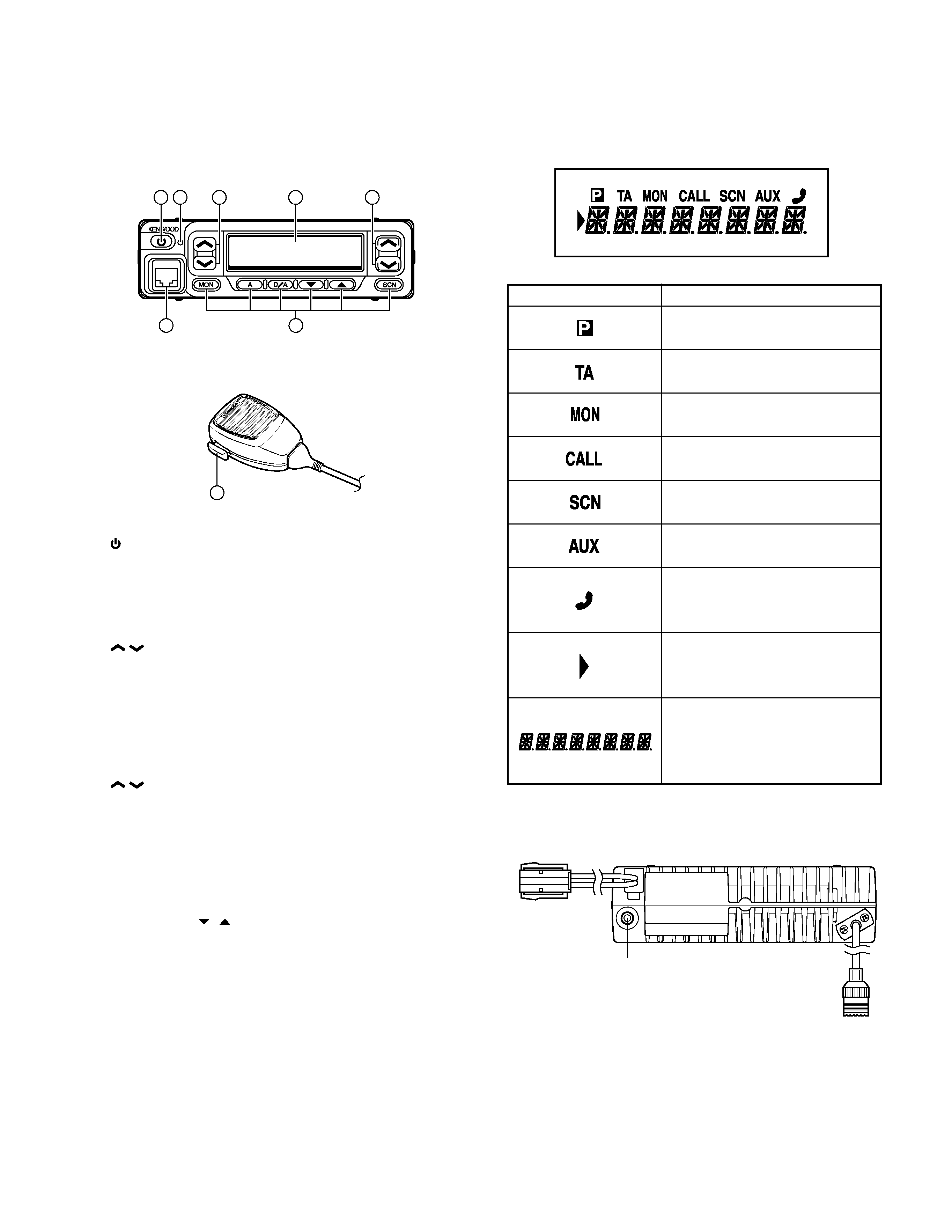
OPERATING FEATURES
· Redial
If you press this key when the system/group is displayed,
the last transmitted DTMF code will appear on the display.
Pressing the PTT switch at this time will transmit the dis-
played DTMF code.
· Scan
Press this key starts scanning. Pressing this key stops
scanning.
· Scan del/add
Used to select whether system scan routines are used
during system scan. Each pressing of the key (to ON)
toggles between lockout and lock. The scan routine is
started when on lock. The DEL indicator flashes when the
system is on lockout.
· Scan temporary delete
This key is temporarily deleted a system being scanned.
If you press this key when scan is stopped (when a call is
being received from another station), the system is tempo-
rarily deleted and scanning restarts.
This key operates even when "Scan Type" is set to "List
Type System Scan".
· System up/down
When the key is pressed each time, the system number
to be selected is incremented/decremented and repeats if
held for one second or longer.
· Telephone disconnect
Pressing this key ends an RIC connection (disconnects
the telephone line).
· Volume up/down
When the key is pressed, the volume level is increased/
decreased and repeats if held for 200ms or longer.
4. Scan Operating
s System Scan
System scan can be selected with the "Scan" key by pro-
gramming the scan feature. When the "Scan" key is
pressed and the "SCN" mark appears, scan mode in en-
tered. Scanning starts from the system following the cur-
rently displayed system. When a call is received, scanning
stops, and the system and group are displayed.
When programming key is touched during scanning, the
scan stops and the revert system or group can be changed.
Scanning resumes one second after the key is released.
There are two types of system scan.
· Fix system scan
All the set systems except locked-out ones are scanned.
If the Del/Add feature is assigned to the programmable key,
it can be controlled from the front panel.

Reviews

There are no reviews of this manual yet.