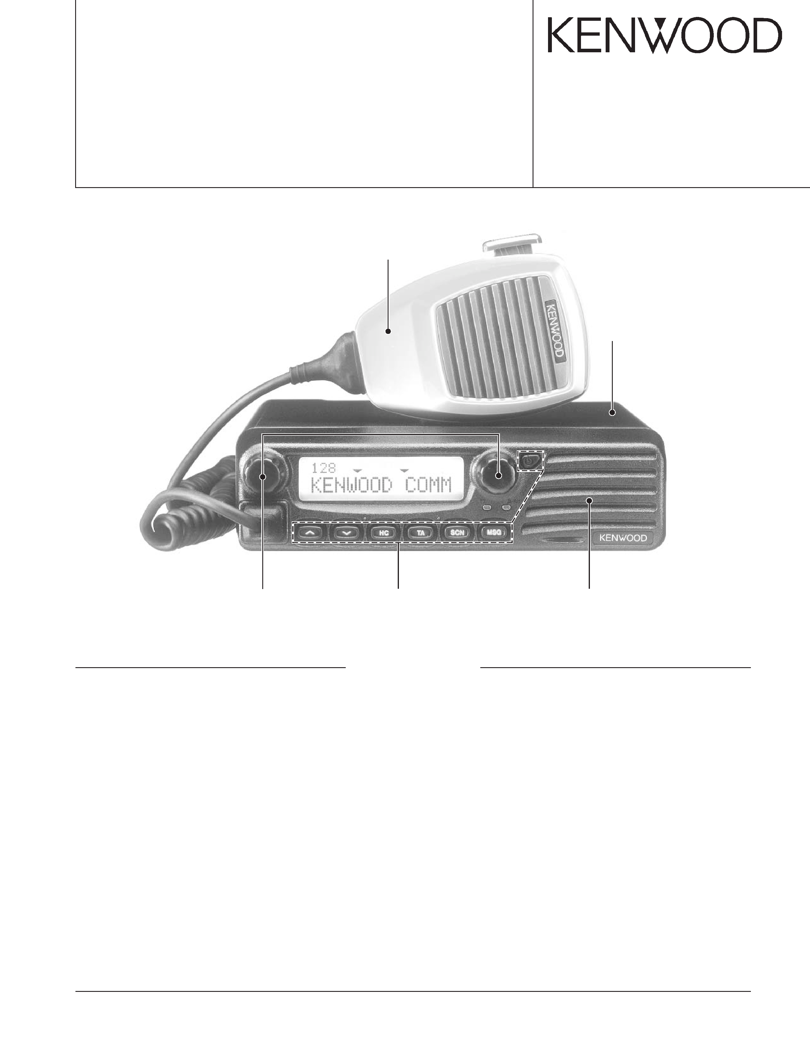
KENWOOD TK-8150 Service Manual

Cover page of KENWOOD TK-8150 Service Manual

Service Manual for KENWOOD TK-8150, downloadable as a PDF file.

We also have owner's manual to this model.

Manual details

  • Immediate download after payment.
  • Delivered as a PDF file.
  • The manual has 58 pages
  • File size: 2.81 MB
  • Available language versions: English
  • Different language versions may vary sligthly in file size and page count.

We guarantee that...

  • our manuals are complete,
  • the manual includes circuit diagrams,
  • our manuals are checked with antivirus,
  • We'll issue refund if the manual is damaged, incomplete or unreadable (our refund policy)

Sample pages

Thumbnail of page 1Thumbnail of page 2Thumbnail of page 3Thumbnail of page 4
Thumbnail of page 5Thumbnail of page 6Thumbnail of page 7Thumbnail of page 8
Thumbnail of page 9
background image
© 2002-10 PRINTED IN JAPAN
B51-8634-00 (N) 743
UHF FM TRANSCEIVER
TK-8150
SERVICE MANUAL
Microphone
(T91-0621-15)
Cabinet
(A01-2185-12)
Panel assy
(A62-1037-03)
Key top
(K29-9222-02)
Knob
(K29-9221-03) x 2
CONTENTS
GENERAL .................................................. 2
SYSTEM SET-UP ...................................... 3
OPERATING FEATURES .......................... 4
REALIGNMENT ......................................... 5
INSTALLATION ......................................... 7
CIRCUIT DESCRIPTION .......................... 12
SEMICONDUCTOR DATA ...................... 16
COMPONENTS DESCRIPTION .............. 20
PARTS LIST ............................................. 22
EXPLODED VIEW .................................... 32
PACKING ................................................. 33
ADJUSTMENT ........................................ 34
PC BOARD
DISPLAY UNIT (X54-3400-10) ............ 45
TX-RX UNIT (X57-6580-10) ................ 49
SCHEMATIC DIAGRAM .......................... 55
BLOCK DIAGRAM ................................... 63
WIRING .................................................... 65
TERMINAL FUNCTION ........................... 66
OPTIONS ................................................. 68
SPECIFICATIONS .................................... 69
background image
TK-8150
2
INTRODUCTION
SCOPE OF THIS MANUAL
This manual is intended for use by experienced techni-
cians familiar with similar types of commercial grade commu-
nications equipment. It contains all required service informa-
tion for the equipment and is current as of this publication
data. Changes which may occur after publication are covered
by either Service Bulletins or Manual Revisions. These are
issued as required.
ORDERING REPLACEMENT PARTS
When ordering replacement parts or equipment informa-
tion, the full part identification number should be included.
This applies to all parts : components, kits, and chassis. If the
part number is not known, include the chassis or kit number
of which it is a part, and a sufficient description of the re-
quired component for proper identification.
PERSONNEL SAFETY
The following precautions are recommended for person-
nel safety :
·DO NOT transmit if someone is within two feet (0.6
meter) of the antenna.
·DO NOT transmit until all RF connectors are verified se-
cure and any open connectors are properly terminated.
· SHUT OFF and DO NOT operate this equipment near
electrical blasting caps or in an explosive atmosphere.
· All equipment should be properly grounded before power-
up for safe operation.
· This equipment should be serviced by a qualified techni-
cians only.
PRE-INSTALLATION CONSIDERNATIONS
1. UNPACKING
Unpack the radio from its shipping container and check for
accessory items. If any item is missing, please contact
KENWOOD immediately.
2. LICENSING REQUIREMENTS
Federal regulations require a station license for each radio
installation (mobile or base) be obtained by the equipment
owner. The licensee is responsible for ensuring transmitter
power, frequency, and deviation are within the limits permit-
ted by the station license.
Transmitter adjustments may be performed only by a li-
censed technician holding an FCC first, second or general
class commercial radiotelephone operator's license. There is
no license required to install or operate the radio.
3. PRE-INSTALLATION CHECKOUT
3-1. Introduction
Each radio is adjusted and tested before shipment. How-
ever, it is recommended that receiver and transmitter opera-
tion be checked for proper operation before installation.
3-2. Testing
The radio should be tested complete with all cabling and
accessories as they will be connected in the final installation.
Transmitter frequency, deviation, and power output should
be checked, as should receiver sensitivity, squelch operation,
and audio output. QT equipment operation should be veri-
fied.
4. PLANNING THE INSTALLATION
4-1. General
Inspect the vehicle and determine how and where the ra-
dio antenna and accessories will be mounted.
Plan cable runs for protection against pinching or crushing
wiring, and radio installation to prevent overheating.
4-2. Antenna
The favored location for an antenna is in the center of a
large, flat conductive area, usually at the roof center. The
trunk lid is preferred, bond the trunk lid and vehicle chassis
using ground straps to ensure the lid is at chassis ground.
4-3. Radio
The universal mount bracket allows the radio to be
mounted in a variety of ways. Be sure the mounting surface
is adequate to support the radio's weight. Allow sufficient
space around the radio for air cooling. Position the radio
close enough to the vehicle operator to permit easy access to
the controls when driving.
4-4. DC Power and wiring
1. This radio may be installed in negative ground electrical
systems only. Reverse polarity will cause the cable fuse
to blow. Check the vehicle ground polarity before installa-
tion to prevent wasted time and effort.
2. Connect the positive power lead directly to the vehicle
battery positive terminal. Connecting the Positive lead to
any other positive voltage source in the vehicle is not rec-
ommended.
CAUTION
If DC power is to be controlled by the vehicle ignition switch,
a switching relay should be used to switch the positive power
lead. The vehicle ignition switch then controls DC to the relay
coil.
3. Connect the ground lead directly to the battery negative
terminal.
4. The cable provided with the radio is sufficient to handle
the maximum radio current demand. If the cable must be
extended, be sure the additional wire is sufficient for the
current to be carried and length of the added lead.
5. INSTALLATION PLANNING ­ CONTROL STATIONS
5-1. Antenna system
Control station. The antenna system selection depends
on many factors and is beyond the scope of this manual.
Your KENWOOD dealer can help you select an antenna sys-
tem that will best serve your particular needs.
GENERAL
background image
TK-8150
3
5-2. Radio location
Select a convenient location for your control station radio
which is as close as practical to the antenna cable entry point.
Secondly, use your system's power supply (which supplies
the voltage and current required for your system). Make sure
sufficient air can flow around the radio and power supply to
allow adequate cooling.
Merchandise received
License and frequency
allocated by FCC
Choose the type of transceiver
Frequency range RF power
Type
450~500MHz
45W
TK-8150 K
Are you using
the remote kit?
YES
KRK-9
Control cable KCT-22
M : 8 feet
M2 : 17 feet
M3 : 25 feet
Are you using
the key label?
Supplied key label
Are you using
the voice scrambler/
ANI?
Modified of control unit
Are you using
the ignition sense
cable?
KCT-18
Are you using
the noise-canceling micro-
phone?
KMC-28A
Supplied microphone
Delivery
Transceiver programming
DC power cable
Supplied cable or
KCT-23 M : 10 feet
KCT-23 M3 : 23 feet
Are you using
the external speaker?
Are you using
the keypad microphone?
YES
YES
YES
External speaker KES-5
YES
YES
KMC-27A
YES
NO
NO
NO
NO
NO
NO
NO
See page 5.
A personal computer (IBM PC or compatible), programming interface (KPG-46),
and programming software (KPG-79D) are required for programming.
See page 8.
See page 7.
See page 9.
See page 7.
See page 7.
DC power supply KPS-10A
Desk top microphone KMC-9C
SERVICE
This radio is designed for easy servicing. Refer to the
schematic diagrams, printed circuit board views, and align-
ment procedures contained in this manual.
GENERAL / SYSTEM SET-UP
SYSTEM SET-UP
Note : There are internal beats in the frequency range of 491.53 to
491.55MHz. Turn the beat shift function ON when you are using these
frequencies.
background image
TK-8150
4
OPERATING FEATURES
1. Controls and Functions
1-1. Front Panel
qw
e
r
!0
t
y
u
o
i!1
!2
1-2. Microphone
!3
q Volume Control
Rotate to adjust the volume level. Clockwise increases
the volume and counterclockwise decreases the volume.
w Display
(See right.)
e Selector
Rotate to select a Zone or CH/GID (channel/group ID).
Clockwise increases the Zone / CH/GID and counterclock-
wise decreases the Zone / CH/GID. The default setting is
CH/GID Up/Down.
r
(Power) switch
Press to switch the transceiver ON. Press and hold for
approximately 1 second to switch the transceiver OFF.
t Microphone Jack
Insert the microphone plug into this jack.
y PF1 Key
Press this key to activate its programmable auxiliary func-
tion. The default setting is Zone Up.
u PF2 Key
Press this key to activate its programmable auxiliary func-
tion. The default setting is Zone Down.
i PF3 Key
Press this key to activate its programmable auxiliary func-
tion. The default setting is None.
o PF4 Key
Press this key to activate its programmable auxiliary func-
tion. The default setting is None.
!0 PF5 Key
Press this key to activate its programmable auxiliary func-
tion. The default setting is None.
!1 PF6 Key
Press this key to activate its programmable auxiliary func-
tion. The default setting is None.
!2 TX / BUSY LEDs
The TX LED lights red while transmitting. In Conventional
Groups, the BUSY LED lights green while receiving.
!3 PTT switch
To transmit, press and hold this switch, then speak into
the microphone. Release to receive.
1-3. Display
Indicator
Description
Displays the zone, group ID, and channel
numbers. Also displays various functions
which have been programmed by your dealer.
CALL
Appears when the squelch opens during a
2-Tone or DTMF call.
MON
Appears when the key programmed as
Monitor is pressed.
Appears when the selected Zone is added to
(left side)
the scan list.
SCN
Appears when you are using Scan mode.
SP
Appears when you are using an external
speaker.
OP
Appears when the optional scrambler board
is installed and activated.
Appears when the selected Channel/Group
(right side)
ID is added to the scan list.
A
Appears when the auxiliary A function is
activated.
B
Appears when the auxiliary B function is
activated.
OS
Appears when Operator Selectable Tone is
activated.
Appears when a FleetSync message is
stored in the transceiver memory. Appears
and blinks when a new message is received.
Displays the zone, group ID, and channel
numbers. Your dealer can program the zone,
group ID, and channel names with up to 12
characters, in place of numbers.
1-4. Rear Panel
SCN SP OP
OS
AB
MON
CALL
Power input
connector
6-pin connector
(for accessories)
25-pin connector
(for accessories)
Antenna
connector
background image
TK-8150
5
REALIGNMENT
1. Modes
3. Panel Test Mode
Setting method refer to "ADJUSTMENT".
4. Panel Tuning Mode
Setting method refer to "ADJUSTMENT".
5. PC Mode
5-1. Preface
The transceiver is programmed by using a personal com-
puter, programming interface (KPG-46) and programming
software (KPG-79D).
The programming software can be used with an IBM PC
or compatible. Figure 1 shows the setup of an IBM PC for
programming.
5-2. Connection Procedure
1. Connect the transceiver to the personal computer with
the interface cable.
2. When the Power switch on, user mode can be entered
immediately. When PC sends command the radio enter
PC mode, and "PROGRAM" is displayed on the LCD.
When data transmitting from transceiver, the red LED is
blinking.
When data receiving to transceiver, the green LED is blink-
ing.
5-3. KPG-46 Description
(PC programming interface cable : Option)
The KPG-46 is required to interface the transceiver to the
computer. It has a circuit in its D-subconnector (25-pin) case
that converts the RS-232C logic level to the TTL level.
The KPG-46 connects the modular microphone jack of the
transceiver to the computers RS-232C serial port.
5-4. Programming Software Description
The KPG-79D programming disk is supplied in 3-1/2" disk
format. The software on this disk allows a user to program
the transceiver radio via programming interface cable (KPG-
46).
Mode
Function
User mode
For normal use.
Panel test mode
Used by the dealer to check the funda-
ment characteristics.
Panel tuning mode
Used by the dealer to tune the radio.
PC mode
Used for communication between the
radio and PC (IBM compatible).
FPU data program-
Used to read and write frequency data and
ming mode
other features to and from the radio.
PC test mode
Used to check the radio using the PC.
This feature is included in the FPU.
See panel tuning.
Firmware program-
Used when changing the main program of
ming mode
the flash memory.
Clone mode
Used to transfer programming data from
one radio to another.
Firmware version
Used to confirm the internal firmware
information
version.
2. How to Enter Each Mode
Mode
Operation
User mode
Power ON
Panel test mode
[PF1]+Power ON
Panel tuning mode
[Panel test mode]+[PF3]
PC mode
Received commands from PC
Firmware programming mode
[PF2]+Power ON
Checksum display mode
[Firmware programming mode]+[PF5]
Clone mode
[PF6]+Power ON
Firmware version information
[PF3]+Power ON (one second)
User mode
Panel test mode
Panel tuning mode
PC mode
FPU data programming mode
Firmware program-
ming mode
PC test mode
PC tuning mode
Checksum
display mode
Clone mode
Firmware version
information
[PF1]+Power on
[PF6]+Power on
[PF3]+Power on
[PF3]
[PF5]
[PF4]
KPG-46 or
KPG-46 +
Tuning cable
(E30-3383-05)
TK-8150
IBM PC
KPG-79D
Fig. 1

Reviews

There are no reviews of this manual yet.