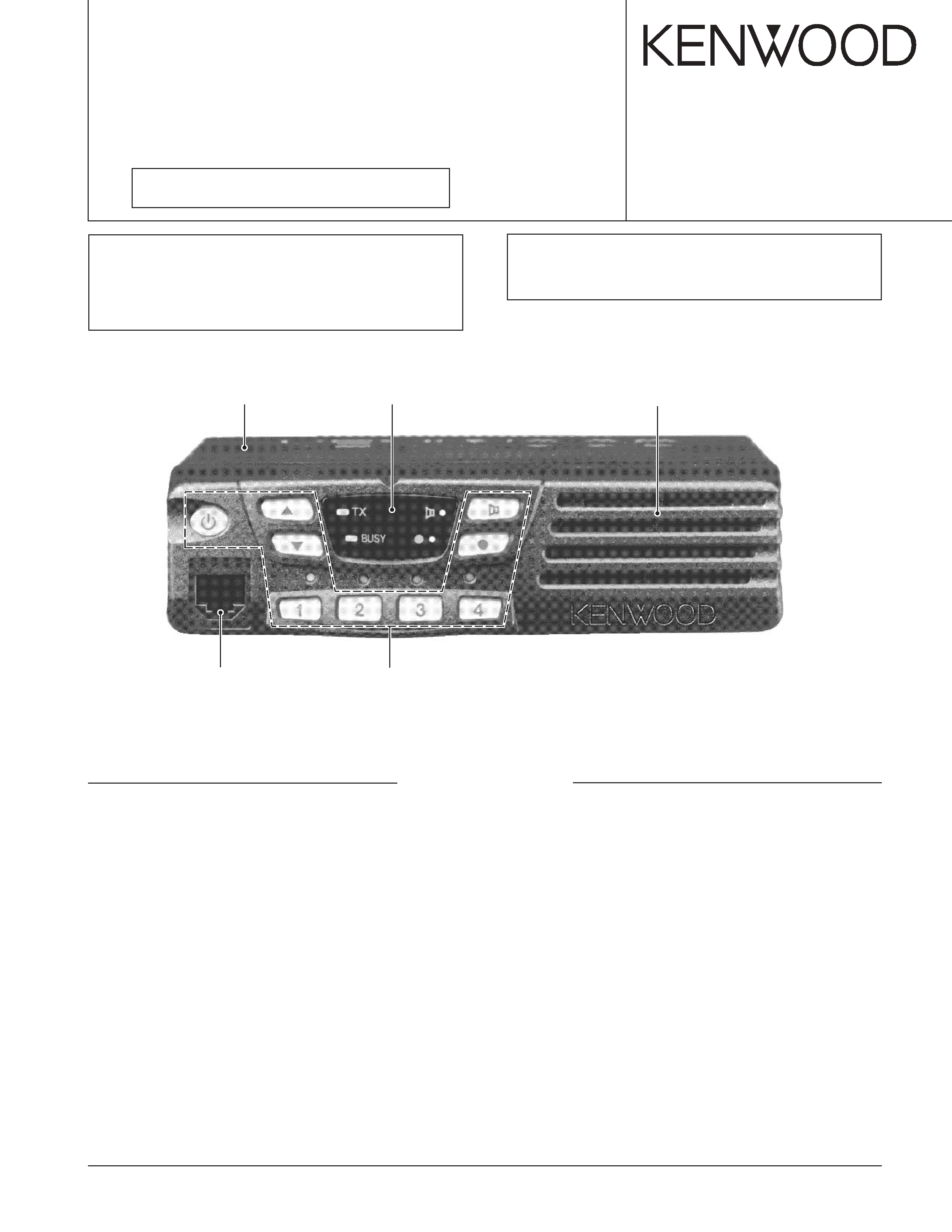
KENWOOD TK8108 Service Manual

Cover page of KENWOOD TK8108 Service Manual

Service Manual for KENWOOD TK8108, downloadable as a PDF file.

Manual details

  • Immediate download after payment.
  • Delivered as a PDF file.
  • The manual has 74 pages
  • File size: 9.55 MB
  • Available language versions: Japanese, English
  • Different language versions may vary sligthly in file size and page count.

We guarantee that...

  • our manuals are complete,
  • the manual includes circuit diagrams,
  • our manuals are checked with antivirus,
  • We'll issue refund if the manual is damaged, incomplete or unreadable (our refund policy)

Sample pages

Thumbnail of page 1Thumbnail of page 2Thumbnail of page 3Thumbnail of page 4
Thumbnail of page 5Thumbnail of page 6Thumbnail of page 7Thumbnail of page 8
Thumbnail of page 9
background image
SERVICE MANUAL /
!
© 2003-11 PRINTED IN JAPAN
B51-8593-10 (N) 621
UHF FM TRANSCEIVER / UHF
TK-8108
Panel assy
(A62-0942-03)
Front glass
(B10-2753-03)
Cabinet
(A01-2178-02)
Key top
(K29-9065-01)
Modular jack
(E08-0877-05)
GENERAL .................................................. 2
SYSTEM SET-UP ...................................... 5
OPERATING FEATURES .......................... 6
REALIGNMENT ....................................... 13
INSTALLATION ....................................... 19
DISASSEMBLY FOR REPAIR ................. 23
CIRCUIT DESCRIPTION .......................... 24
SEMICONDUCTOR DATA ...................... 32
COMPONENTS DESCRIPTION .............. 34
PARTS LIST ............................................. 36
EXPLODED VIEW .................................... 42
CONTENTS
REVISED /
This service manual applies to products with 50800001 or
subsequent serial numbers.
In terms of the products with the serial numbers earlier
than 50800001, refer to the TK-8108 service manual as per
part No. B51-8593-00 or B51-8637-00.
PACKING ................................................. 43
ADJUSTMENT ........................................ 45
TERMINAL FUNCTION ........................... 52
PC BOARD
DISPLAY UNIT (X54-3460-20) ............ 54
TX-RX UNIT (X57-6923-XX) ............... 56
SCHEMATIC DIAGRAM .......................... 60
BLOCK DIAGRAM ................................... 64
LEVEL DIAGRAM .................................... 66
SPECIFICATION ...................................... 68
!"#$%RMUMMMMN
!"#$%&
RMUMMMMN=
!"#$%&'()"*=_RNJURVPJ
MM
_RNJUSPTJMM
qhJUNMU
!"
background image
TK-8108
2
Service Manual List
Title
Parts number
Remarks
Destination
TX-RX unit number
Display unit number
TK-8108
B51-8593-00
C, C3
X57-6303-XX
X54-3340-20
TK-8108
B51-8637-00
PDF only
M
X57-6303-01
X54-3340-20
TK-8108
B51-8593-10
REVISED
C, C3, M
X57-6923-XX
X54-3460-20
(This service manual)
GENERAL /
INTRODUCTION
SCOPE OF THIS MANUAL
This manual is intended for use by experienced techni-
cians familiar with similar types of commercial grade commu-
nications equipment. It contains all required service informa-
tion for the equipment and is current as of this publication
date. Changes which may occur after publication are covered
by either Service Bulletins or Manual Revisions, which are
issued as required.
ORDERING REPLACEMENT PARTS
When ordering replacement parts or equipment informa-
tion, the full part identification number should be included.
This applies to all parts : components, kits, and chassis. If the
part number is not known, include the chassis or kit number
of which it is a part and a sufficient description of the required
component for proper identification.
PERSONAL SAFETY
The following precautions are recommended for personal
safety :
·DO NOT transmit if someone is within two feet (0.6
meter) of the antenna.
!"#
!"#$%&'()*+,-./01234567
!"#$%&'()*+,- ./01234567
!"#$%&'()*+,-.*$/01234567
!"#$%&'()
!"#$
!"#$%&'()*+,-./01#$23456
!"#$%&'()"*+",-./01234!"
!"#$%&'(!)*+,-./01 23
!
!"#$%&'()*+,
!
!"#$%&'()*+,-
!"#$%&'=EMKS= F=
!"#$%&'()*
KKKKKKKKKKKKKKKKKKKKKKKKKKKKKKKKKKKKKKKKKKKKKKKKKKKKKKKKKKKKKKKKKKKKKKK O
KKKKKKKKKKKKKKKKKKKKKKKKKKKKKKKKKKKKKKKKKKKKKKKKKKKKKKKKKKKKKKKKKKKKKKK R
! KKKKKKKKKKKKKKKKKKKKKKKKKKKKKKKKKKKKKKKKKKKKKKKKKKKKKKKKKKKKKKKKKKKKKKK S
! KKKKKKKKKKKKKKKKKKKKKKKKKKKKKKKKKKKKKKKKKKKKKKKKKKKKKKKKKKKKKKKKKKKKK NP
====
KKKKKKKKKKKKKKKKKKKKKKKKKKKKKKKKKKKKKKKKKKKKKKKKKKKKKKKKKKKKKKKKKKKKKKKK NV
!"#$ KKKKKKKKKKKKKKKKKKKKKKKKKKKKKKKKKKKKKKKKKKKKKKKKKKKKKK OP
! KKKKKKKKKKKKKKKKKKKKKKKKKKKKKKKKKKKKKKKKKKKKKKKKKKKKKKKKKKKKKKKKKKKK OQ
!"KKKKKKKKKKKKKKKKKKKKKKKKKKKKKKKKKKKKKKKKKKKKKKKKKKKKKKKKKKKKKKKK PP
! KKKKKKKKKKKKKKKKKKKKKKKKKKKKKKKKKKKKKKKKKKKKKKKKKKKKKKKKKKKKKKKKKKKK PR
KKKKKKKKKKKKKKKKKKKKKKKKKKKKKKKKKKKKKKKKKKKKKKKKKKKKKKKKKKKKKKKKKKKK PS
!"KKKKKKKKKKKKKKKKKKKKKKKKKKKKKKKKKKKKKKKKKKKKKKKKKKKKKKKKKKKKKKKK QO
KKKKKKKKKKKKKKKKKKKKKKKKKKKKKKKKKKKKKKKKKKKKKKKKKKKKKKKKKKKKKKKKKKKK QP
KKKKKKKKKKKKKKKKKKKKKKKKKKKKKKKKKKKKKKKKKKKKKKKKKKKKKKKKKKKKKKKKKKKK QS
! KKKKKKKKKKKKKKKKKKKKKKKKKKKKKKKKKKKKKKKKKKKKKKKKKKKKKKKKKKKKKKKKKKKK RP
m`
==afpmi^v=rkfq=EuRQJPQSMJOMF KKKKKKKKKKKKKKKK RQ
==quJou=rkfq=EuRTJSVOPJuuF KKKKKKKKKKKKKKKKKKKKK RS
KKKKKKKKKKKKKKKKKKKKKKKKKKKKKKKKKKKKKKKKKKKKKKKKKKKKKKKKKKKKKKKKKKKK SM
KKKKKKKKKKKKKKKKKKKKKKKKKKKKKKKKKKKKKKKKKKKKKKKKKKKKKKKKKKKKKKKKKKKK SQ
KKKKKKKKKKKKKKKKKKKKKKKKKKKKKKKKKKKKKKKKKKKKKKKKKKKKKKKKKKKKKKKKKKKK SS
KKKKKKKKKKKKKKKKKKKKKKKKKKKKKKKKKKKKKKKKKKKKKKKKKKKKKKKKKKKKKKKKKKKK SV
background image
TK-8108
3
·DO NOT transmit until all RF connectors are secure and
any open connectors are properly terminated.
· SHUT OFF this equipment when near electrical blasting
caps or while in an explosive atmosphere.
· All equipment should be properly grounded before power-
up for safe operation.
· This equipment should be serviced by only qualified tech-
nicians.
PRE-INSTALLATION CONSIDERATIONS
1. UNPACKING
Unpack the radio from its shipping container and check for
accessory items. If any item is missing, please contact
KENWOOD immediately.
2. LICENSING REQUIREMENTS
Federal regulations require a station license for each radio
installation (mobile or base) be obtained by the equipment
owner. The licensee is responsible for ensuring transmitter
power, frequency, and deviation are within the limits permit-
ted by the station license.
Transmitter adjustments may be performed only by a li-
censed technician holding an FCC first, second or general
class commercial radiotelephone operator's license. There is
no license required to install or operate the radio.
3. PRE-INSTALLATION CHECKOUT
3-1. Introduction
Each radio is adjusted and tested before shipment. How-
ever, it is recommended that receiver and transmitter opera-
tion be checked for proper operation before installation.
3-2. Testing
The radio should be tested complete with all cabling and
accessories as they will be connected in the final installation.
Transmitter frequency, deviation, and power output should
be checked, as should receiver sensitivity, squelch operation,
and audio output. Signalling equipment operation should be
verified.
4. PLANNING THE INSTALLATION
4-1. General
Inspect the vehicle and determine how and where the ra-
dio antenna and accessories will be mounted.
Plan cable runs for protection against pinching or crushing
wiring, and radio installation to prevent overheating.
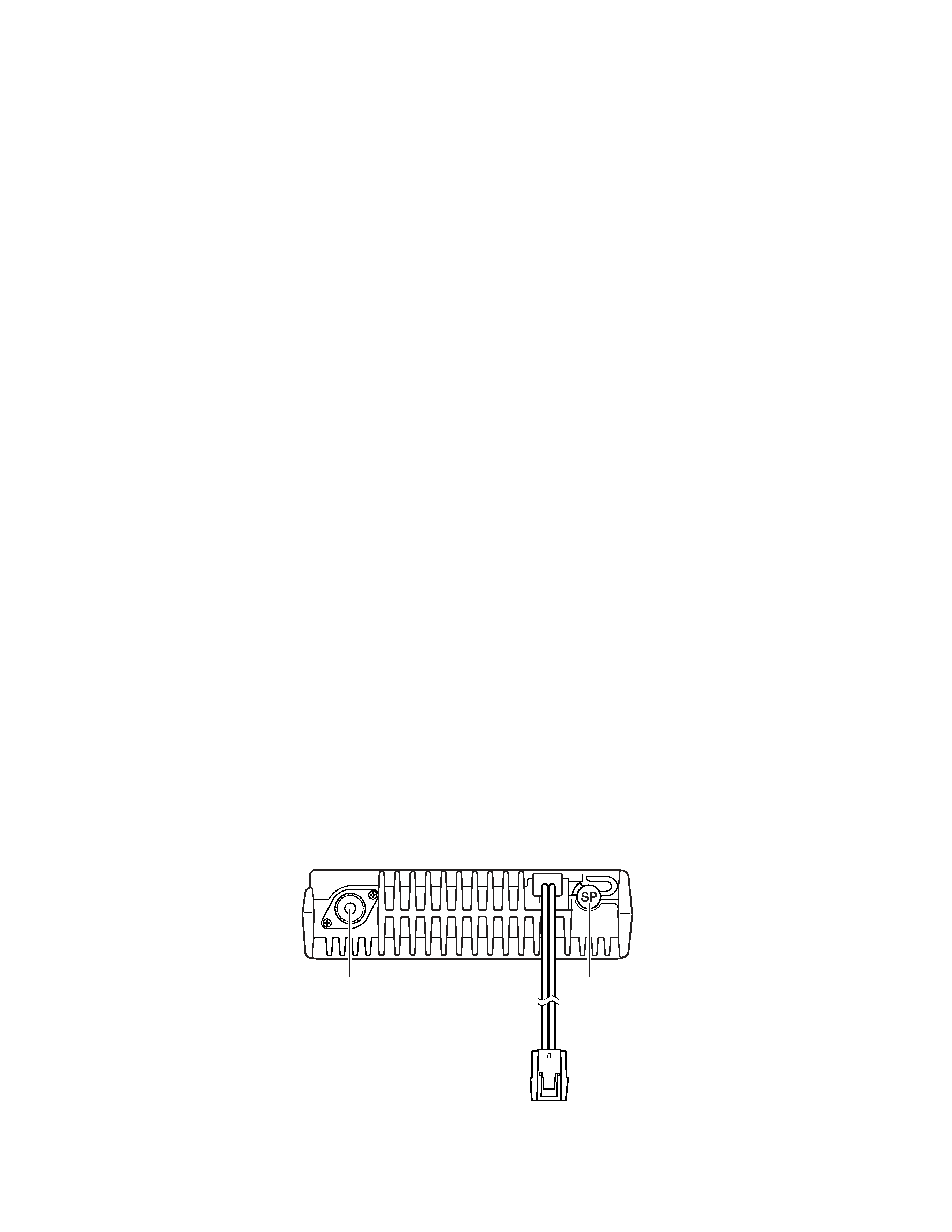
4-2. Antenna
The favored location for an antenna is in the center of a
large, flat conductive area, usually at the roof center. The
trunk lid is preferred, bond the trunk lid and vehicle chassis
using ground straps to ensure the lid is at chassis ground.
4-3. Radio
The universal mount bracket allows the radio to be
mounted in a variety of ways. Be sure the mounting surface
is adequate to support the radio's weight. Allow sufficient
space around the radio for air cooling. Position the radio close
enough to the vehicle operator to permit easy access to the
controls when driving.
!"#$% &'()*+, -./0123()
!"#$%&'()*+,-./01
!"#$ %&'()*+,-./012-345
!"
!"#$%&'()*+,-./0123'456
!"#$%&'()*+,-./01
!"
NK=
!"#$%&'()*+,-./01234567
!"#$%hbktlla
OK=
!"
!"#$%&'()*+,-./0123456=E
! F=
!"#$% !"&'()*+,-./0
!"#$%&'()*$+,-./
!"#$%&'()c``
! "#$%&'(
!"#$%&'()*+,-./0123 !045
!"#$%&
PK=
!"
PJNK=
!"#$%&'()*+,-./0123456
!"#$%&'()*+,-./0
PJOK=
!"#$%& '()*+,-./0123456
!"#$%&'()*(+,-./)*01"#$%2
!"#$%&'()*+,-./012*
QK=
!"
QJNK=
!"#$%&'()&*+,-./0.1234
!"#$%&'()*+,-./&012/!34
!
QJOK=
!"#$%&'()*+,-./012 34,5
!"#$%&'!()*+,-./01%&'!
!"#$%&'()*+,-.
QJPK=
!"
!"#$%&'()* !+,-./012 !3
!"#$%&'()*+,$%&'()-./012
!"#$%&'()*+,-./01234567
!"#$%&'()*+,-.
GENERAL /
background image
TK-8108
4
4-4. DC Power and wiring
1. This radio may be installed in negative ground electrical
systems only. Reverse polarity will cause the cable fuse to
blow. Check the vehicle ground polarity before installation
to prevent wasted time and effort.
2. Connect the positive power lead directly to the vehicle
battery positive terminal. Connecting the Positive lead to
any other positive voltage source in the vehicle is not rec-
ommended.
3. Connect the ground lead directly to the battery negative
terminal.
4. The cable provided with the radio is sufficient to handle
the maximum radio current demand. If the cable must be
extended, be sure the additional wire is sufficient for the
current to be carried and length of the added lead.
5. INSTALLATION PLANNING ­ CONTROL STATIONS
5-1. Antenna system
Control station. The antenna system selection depends on
many factors and is beyond the scope of this manual. Your
KENWOOD dealer can help you select an antenna system
that will best serve your particular needs.
5-2. Radio location
Select a convenient location for your control station radio
which is as close as practical to the antenna cable entry point.
Secondly, use your system's power supply (which supplies
the voltage and current required for your system). Make sure
sufficient air can flow around the radio and power supply to
allow adequate cooling.
SERVICE
This radio is designed for easy servicing. Refer to the
schematic diagrams, printed circuit board views, and align-
ment procedures contained in this manual.
NOTE
If you do not intend to use the 3.5-mm jack for the external
speaker, fit the supplied speaker-jack cap to stop dust and
sand from getting in.
QJQK=
!"#$
NK
!"#$%&'()*+,-!./01234+5
!"#$%&'()*+,-./01234567
!"#$%&'()*+
OK
!"#$%&'(')*+,!"#-./012
!"#$%&'()
*+,-.
PK
!"#$%&'()*+
QK
!"#$%&'(!)*+,-.(/0
!!
!"#$%&'()*+,&-"./0123-"
!"#$%&'
RK=
!J
RJNK=
!
!"#$%&'()*+,-./012%34 5
hbktlla
!"#$%&'()*+,%&-./
!"#$
RJOK=
!"
!"#$%&'()*+,-.!/012/034
!"#$%&'()*+,,-./0"1=E
!"#$%&$'F
!"#$%&'()*+
!"#$%&'(
!
!"#$%&'() *+,"#-./0'12 3
!"#$%&'!()*+,-./012345
!
PKRãã
!"#$%&'()&*+, !"#$-.
!"#$%&'(
GENERAL /
Speaker
jack cap
Power input
connector
Antenna connector
background image
TK-8108
5
SYSTEM SET-UP /
Merchandise received
Choose the type of transceiver
Transceiver programming
KCT-39
Connection cable
KCT-18
Ignition sense cable
KCT-36
Extension cable
KDS-100
Mobile data
terminal
KGP-2A
Modem GPS receiver or
KGP-2B
Modem GPS controller
KES-3
External speaker
See page 13.
A personal computer (IBM PC or compatible), programming interface (KPG-46),
and programming software (KPG-70D) are required for programming.
Frequency range (MHz)
RF power
Type
450~490
25W
C,M
400~430
25W
C3
(Option)
(Option)
(Option)
(Option)
(Option)
(Option)
or
Delivery
KCT-39
KCT-18
KCT-36
KDS-100
KGP-2A
Modem GPS
KGP-2B
Modem GPS
KES-3
13
(IBM PC)
(KPG-46)(KPG-70D)
(MHz)
400~430
25W
C3
450~490
25W
C,M
()
()
()
()
()
()
or

Reviews

There are no reviews of this manual yet.